Chapter:
Carnot engine - Essential parts, Working, four stages of operations

Carnot engine
Heat engine is a device which converts heat energy
into mechanical energy.
In the year 1824, Carnot devised
an ideal cycle of operation for a heat engine. The machine used for realising
this ideal cycle of
operation is called an ideal heat
engine or carnot heat engine.
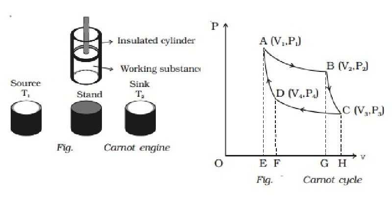
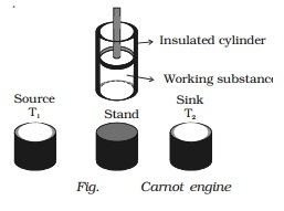
The essential parts of a Carnot
engine are shown in Fig..

(i) Source
It is a hot body which is kept at
a constant temperature T1. It has infinite thermal capacity. Any amount of heat
can be drawn from it at a constant temperature T1 (i.e) its temperature will
remain the same even after drawing any amount of heat from it.
(ii) Sink
It is a cold body which is kept
at a constant lower temperature T2.
Its thermal capacity is also infinite that any amount of heat added to it will
not increase its temperature.
(iii) Cylinder
Cylinder is made up of
non-conducting walls and conducting bottom. A perfect gas is used as a working
substance. The cylinder is fitted with a perfectly non-conducting and
frcitionless piston.
(iv) Insulating stand
It is made up of non conducting
material so as to perform adiabatic operations.
Working : The Carnot engine has the following four stages of operations.
1. Isothermal expansion 2.
Adiabatic expansion 3. Isothermal compression 4. Adiabatic compression.
Isothermal expansion
Let us consider one mole of an
ideal gas enclosed in the cylinder. Let V1,
P1 be the initial volume
and pressure of the gas respectively. The initial state of the gas is
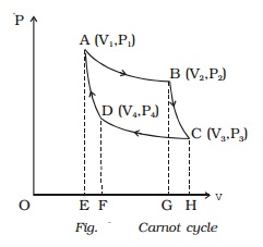
represented by the point A on the P?V diagram. The cylinder is placed over
the source which is at the temperature T1.

The piston is allowed to move
slowly outwards, so that the gas expands. Heat is gained from the source and
the process is isothermal at constant temperature T1. In this process the volume of the gas changes from
V1 to V2 and the pressure changes from P1 to P2. This process is represented by
AB in the indicator diagram (Fig.).
During this process, the quantity
of heat absorbed from the source is Q1 and W1 is the corresponding amount of
work done by the gas.
Q1 = W1 = ∫v1v2PdV
= RT1loge(V2/V1) = area ABGEA
...(1)
Adiabatic expansion
The cylinder is taken from the
source and is placed on the insulting stand and the piston is moved further so
that the volume of the gas changes from V2
to V3 and the pressure
changes from P2 to P3. This adiabatic expansion
is represented by BC. Since the gas is thermally insulated from all sides no
heat can be gained from the surroundings. The temperature of the gas falls from
T1 to T2.
Let W2 be the work done by the gas in expanding
adiabatically.
∴ W2 = ∫v1v2PdV = R/(γ-1) . (T1-T2)=
Area BCHGB ...(2)
Isothermal compression
The cylinder is now placed on the
sink at a temperature T2.
The piston is moved slowly downward to compress the gas isothermally. This is
represented by CD. Let (V4, P4)
be the volume and pressure corresponding to the point D. Since the base of the
cylinder is conducting the heat produced during compression will pass to the
sink so that, the temperature of the gas remains constant at T2. Let Q2 be the amount of heat rejected to the sink and W3 be the amount of work done
on the gas in compressing it isothermally.
Q2 = W3 = ∫v1v2-PdV
= -RT2loge(V4/V3) = - area ABGEA
...(1)
The negative sign indicates that
work is done on the working substance.
Q2 = RT2
loge(V3/V4)
Adiabatic compression
The cylinder is now placed on the
insulating stand and the piston is further moved down in such a way that the
gas is compressed adiabatically to its initial volume V1 and pressure P1.
As the gas is insulated from all sides heat produced raises the temperature of
the gas to T1. This change
is adiabatic and is represented by DA.
Let W4 be the work done on
the gas in compressing it adiabatically from a state D (V4 , P4) to the initial state A (V1, P1).
∴ W4 = - ∫v1v2PdV = -R/(γ-1) . (T1-T2)=
Area BCHGB ...(4)
The negative sign indicates that
work is done on the working substance.
Work done by the engine per cycle
Total work done by the gas during
one cycle of operation is (W1 + W2).
Total work done on the gas during
one cycle of operation is (W3 + W4).
∴ Net work done by the gas in a complete cycle
W = W1 + W2
? (W3 + W4)
But W2 = W4
∴ W = W1 ? W3
W = Q1 ? Q2
Also, W = Area ABGEA + Area BCHGB
- Area CDFHC - Area DAEFD
(i.e) W = Area ABCDA
Hence in Carnot heat engine, net
work done by the gas per cycle is numerically equal to the area of the loop
representing the cycle.
Efficiency of Carnot?s engine
η= Heat converted into work
/ Heat drawn from the source = Q1-Q2/Q1
η= 1 ? Q2/Q1
But
Q1/Q2 = W1/W3 = RT1log(V2/V1) / RT2log(V3/V4)
= T1log(V2/V1) / T2log(V3/V4) ???(5)
Since B and C lie on the same
adiabatic curve BC
T1V2γ-1
= T2V3γ-1 (∵ TVγ - 1 = constant)
where γ = Cp/Cv
T1/T2 = V3γ-1
/ V2γ-1
???(6)
Similarly D & A lie on the
same adiabatic curve DA
T1V1γ-1
= T2V4γ-1
T1/T2 = V4γ-1
/ V1γ-1
???(7)
From (6) & (7)
V3γ-1 / V2γ-1
= V4γ-1 / V1γ-1
V3/V2 = V4/V1
Or
V2/V1 = V3/V4 ?????..(8)
substituting equation (8) in
equation (5)
(i.e) Q1/Q2
= T2/T1
We have η= 1-(Q2/Q1)
= 1-(T2/T1)
η= T1-T2 /
T1
Inferences
Efficiency of Carnot?s cycle is
independent of the working substance, but depends upon the temperatures of heat
source and sink.
Efficiency of Carnot?s cycle will
be 100% if T1 = ∞ or T2 = 0 K. As neither the temperature of heat source can
be made infinite, nor the temperature of the sink can be made 0 K, the
inference is that the Carnot heat engine working on the reversible cycle cannot
have 100% efficiency.
Related Topics