Magnetism and Electromagnetism | Physics | Science - Answer the following questions | 9th Science : Physics : Magnetism and Electromagnetism
Chapter: 9th Science : Physics : Magnetism and Electromagnetism
Answer the following questions
MAGNETISM
AND ELECTROMAGNETISM
TEXT BOOK EXERCISES
V. Answer in brief:
1. State Fleming’s Left Hand
Rule.
Answer: The law
states that while stretching the three fingers of left hand in perpendicular
manner with each other, if the direction of the current is denoted by middle
finger of the left hand and the second finger is for direction of the magnetic
field then the thumb of the left hand denotes the direction of the force or
movement of the conductor.
2. Define magnetic flux density.
Answer: The
number of magnetic field lines crossing unit area kept normal to the direction
of field lines is called magnetic flux density. Its unit is Wb/m2.
3. List the main parts of an
electric motor.
Answer:
Main parts of an
electric motor
(i)
Field magnet.
(ii)
Armature (Rectangular coil)
(iii)
Split ring (Commutator)
(iv)
Brushes
(v)
Battery
4. Draw and label the diagram of
an AC generator.
Answer:
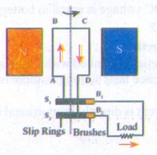
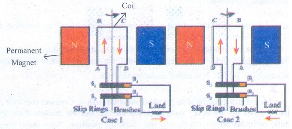
PARTS
N,
S - Permanent magnet
A
B C D - Rectangular coil or armature.
S1
, S2 - Slip rings
B1
, B2 - Carbon brushes
5. State the advantages of ac
over dc.
Answer:
(i)
The cost of generation of AC is less than the cost of generation of DC.
(ii)
AC can be easily converted into D.C.
(iii)
Only alternating voltage can be stepped up or stepped down by using a
transformer.
(iv)
AC can be transmitted to distant places without much loss of electric power
than DC.
6. Differentiate step up and step
down transformer.
Answer:
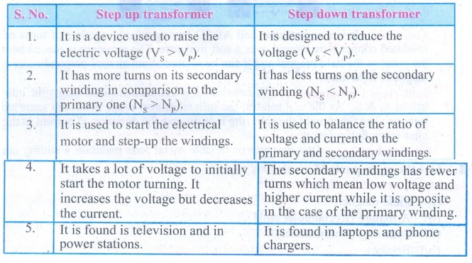
Step up transformer
1.
It is a device used to raise the electric voltage (Vs > Vp).
2.
It has more turns on its secondary winding in comparison to the primary one (Ns
> Np).
3.
It is used to start the electrical motor and step-up the windings.
4.
It takes a lot of voltage to initially start the motor turning. It increases
the voltage but decreases the current.
5.
It is found is television and in power stations.
Step down
transformer
1.
It is designed to reduce the voltage (Vs < Vp).
2.
It has less turns on the secondary winding (Ns < Np).
3.
It is used to balance the ratio of voltage and current on the primary and
secondary windings.
4.
The secondary windings has fewer turns which mean low voltage and higher
current while it is opposite in the case of the primary winding.
5.
It is found in laptops and phone chargers.
7. A portable radio has a built
in transformer so that it can work from the mains instead of batteries. Is this
a step up or step down transformer? Give reason.
Answer: It is a
step down transformer. So that rectified DC voltage is equal to battery
voltage, hence it can work on mains as well as on battery.
8. State Faraday’s laws of
electromagnetic induction.
Answer:
First law: Whenever
there is a change in magnetic flux linked with a coil, an electric current is
induced. The induced potential difference lasts so long as there is a change in
the magnetic flux linked with the coil.
Second law: The
magnitude of the induced current is directly proportional to the rate of change
of magnetic flux linked with the coil.
VI. Answer in detail:
1. Explain the principle,
construction and working of a dc motor.
Answer:
Principle: An electric motor works
on the principle that a current carrying conductor placed in a magnetic field
experiences a force. The direction of force is given by Fleming's left hand
rule.
Construction: An
electric motor consists of the following main parts:
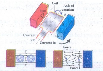
Armature: It is a rectangular coil
ABCD having a large number of turns of this insulated copper wire wound over a
soft iron core. The armature is placed between the poles of the field magnet
and it can be rotated about an axis perpendicular to the magnetic field lines.
Split rings
(commutators): It consists of a cylindrical metal ring split
into two halves S1 & S2. As the coil rotates, the
split rings also rotate about the same axis of rotation. The function of the
split ring is to reverse the direction of current in the coil after every half
rotation.
Carbon brushes: Two
graphite or flexible metal rods maintain a sliding contact with split rings S1
and S2 alternately.
Battery: A
battery of few cells is connected to the brushes. The current from the battery
flows to the armature coil through the brushes and the split rings.
Working: A simple
coil is placed inside two poles of a magnet. Now look at the current carrying
conductor segment AB. The direction of the current is towards B, whereas in the
conductor segment CD the direction is opposite. As the current is flowing in
opposite directions in the segments AB and CD, the direction of the motion of
the segments would be in opposite directions according to Fleming’s left hand
rule. When two ends of the coil experience force in opposite direction, they
rotate. If the current flow is along the line ABCD, then the coil will rotate
in clockwise direction first and then in anticlockwise direction. If we want to
make the coil rotate in any one direction, say clockwise, then the direction of
the current should be along ABCD in the first half of the rotation and along
DCBA in the second half of the rotation.
When
the gap in the split ring commutator is aligned with terminals X and Y there is
no flow of current in the coil. But, as the coil is moving, it continues to
move forward bringing one of the split ring commutator in contact with the
carbon brushes X and Y. The reversing of the current is repeated at each half
rotation, giving rise to a continuous rotation of the coil.
2. Explain two types of transformer.
Answer:
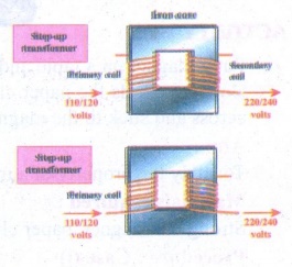
Step up transformer: The
transformer used to change a low alternative voltage to a high alternating
voltage is called a step up transformer. ie (Vs >Vp).
In a step up transformer, the number of turns in the secondary coil is more
than the number of turns in the primary coil (Ns > Np).
Step down
transformer: The transformer used to change a high alternating
voltage to a low alternating voltage is called a step down transformer (Vs< Vp).
In a step down transformer, the number of turns in the secondary coils are less
than the number of turns in the primary coil (Ns <Np).
3. Draw a neat diagram of an AC
generator and explain its working.
Answer:
(i)
An alternating current (AC) generator, as shown in, consists of a rotating
rectangular coil ABCD called armature placed between the two poles of a
permanent magnet.
(ii)
The two ends of this coil are connected to two slip rings S1 and S2.
The inner sides of these rings are insulated.
(iii)
Two conducting stationary brushes B1 and B2 are kept
separately on the rings S1 and S2 respectively.
(iv)
The two rings S1 and S2 are internally attached to an
axle.
(v)
The axle may be mechanically rotated from outside to rotate the coil inside the
magnetic field. Outer ends of the two brushes are connected to the external
circuit.
(vi)
When the coil is rotated, the magnetic flux linked with the coil changes. This
change in magnetic flux will lead to generation of induced current.
(vii)
The direction of the induced current, as given by Fleming’s Right Hand Rule, is
along ABCD in the coil and in the outer circuit it flows from B2 to B1.
(viii)
During the second half of rotation, the direction of current is along DCBA in
the coil and in the outer circuit it flows from B1 to B2.
(ix)
As the rotation of the coil continues, the induced current in the external
circuit is changing its direction for every half a rotation of the coil.
Intext Activities
ACTIVITY - 1
Put a magnet on a table and place
some paper clips nearby. If you push the magnet slowly towards the paper clips,
there will be a point at which the paper clips jump across and stick to the
magnet. What do you understand from this?
Aim:
To
study the property of a magnet.
Materials required:
Strong
bar magnet, paper clips.
Procedure: Case (i)
(i)
Put a bar magnet on a table and place some paper clips nearby.
(ii)
If you push the magnet slowly towards the paper clips, there will be a point at
which the paper clips jump across and stick to the magnet. What do you
understand from this?
Conclusion:
(i)
From the above activity, we can conclude that magnets have an invisible field
all around them which attracts magnetic materials.
(ii)
In this space we can feel the force of attraction or repulsion due to the
magnet.
(iii)
Thus magnetic field is the region around the magnet where its magnetic influence
can be felt. It is called as magnetic field.
ACTIVITY - 2
Take a cardboard and thread a
wire perpendicular through it. Connect the wire such that current flows up the
wire. Switch on the circuit. Let the current flow. Place a magnetic compass on
the cardboard and mark the position. Now move magnet and mark the new position.
If you join all the points you will find that it is a circle. Reverse the
direction of the current, you will find the magnetic circles are clockwise.
Aim:
To
observe the magnetic field around a straight conductor carrying current.
Materials required:
Thick
copper wire (conductor), some connecting wires, battery, key, white cardboard,
magnetic compass.
Procedure:
(i)
Fix a white cardboard horizontally.
(ii)
Make a small hole at its centre.
(iii)
Pass the thick copper wire through the hole, perpendicular to the cardboard.
(iv)
Join the ends of the thick copper wire to a battery and a key with the help of
some connecting wires.
(v)
Switch on the circuit. Let the current flow.
(vi)
Place a magnetic compass on the cardboard.
(vii)
Mark S and N point of the compass X and Y respectively on the cardboard.
(viii)
Move the compass such that S end touches Y.
(ix)
Now mark the N end as Z. In the next step move the compass such that S end
touch Z. Repeat the steps.
(x)
Now join all the points. What do you observe?
(xi)
Now keep the compass away from the centre and follow.
Observation:
(i)
It is seen that it is a circle.
(ii)
We can draw another magnetic line and the magnetic lines are concentric circles
and also we will find the magnetic lines are anti-clockwise.
(iii)
When the direction of current is reversed, the direction of magnetic lines of force
are clockwise.
ACTIVITY-3
Create your own
electromagnet
You are given a long iron nail,
insulation coated copper wire and a battery. Can you make your own
electromagnet?
Aim:
To
create your own electromagnet.
Materials required:
Iron
nail, insulated coated copped wire, battery and paper clips.
Procedure:
(i)
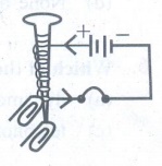
Take an iron nail, wind ten or more loops of insulated copper wire around it.
However, make sure not to be make the diameter of the loop more than a
centimetre in width.
(ii)
Connect the ends of the wire to a key and a battery.
(iii)
Switch on the key and bring some paper clips close to the nail.
(iv) Switch off the key. What do you observe?
Observation:
When
the key is switched on, the electromagnet attracts the paper clips due to the
current flowing through the coil wound around the iron nail. When the key is
switched off, the paper clips detach from the iron nail.
Conclusion:
Thus
an electro magnet is a temporary magnet which behaves as a magnet in the
presence of electric current.
Related Topics