Chapter: CiIvil Surveying : Theodolite Surveying
Theodolite Surveying
THEODOLITE
A theodolite is essentially a transit of high precision. Theodolites come in different sizes and weights and from different manufacturers. Although theodolites may differ in appearance, they are basically alike in their essential parts and operation. Some of the models currently available for use in the military are WILD (Herrbrugg), BRUNSON, K&E, (Keuffel & Esser), and PATH theodolites.
To give you an idea of how a theodolite differs from a transit, we will discuss some of the most commonly used theodolites in the U.S. Armed Forces.
One-Minute Theodolite
The 1-min directional theodolite is essentially a directional type of instrument. This type of instrument can be used, however, to observe horizontal and vertical angles, as a transit does.
The theodolite shown in figure 11-12 is a compact, lightweight, dustproof, optical reading instrument. The scales read directly to the nearest minute or 0.2 mil and are illuminated by either natural or artificial light. The main or essential parts of this type of theodolite are discussed in the next several paragraphs.
HORIZONTAL MOTION
Located on the lower portion of the alidade,
and adjacent to each other, are the horizontal motion clamp and tangent screw
used for moving the theodolite in azimuth. Located on the horizontal circle
casting is a horizontal circle clamp that fastens the circle to the alidade.
When this horizontal (repeating) circle clamp is in the lever-down position,
the horizontal circle turns with the telescope. With the circle clamp in the
lever-up position, the circle is unclamped and the telescope turns
independently. This combination permits use of the theodolite as a REPEATING
INSTRUMENT. To use the theodolite as a DIRECTIONAL TYPE OF INSTRUMENT, you
should use the circle clamp only to set the initial reading. You should set an
initial reading of 0 o 30� on the plates when a direct and reverse (D/R) pointing
is required. This
will
minimize the possibility of ending the D/R pointing with a negative value.
VERTICAL MOTION
.- Located on the standard opposite the vertical circle are the
vertical motion clamp and tangent screw. The tangent screw is located on the
lower left and at right angles to the clamp. The telescope can be rotated in
the vertical plane completely around the axis (360 o ).
LEVELS.- The
level vials on a theodolite are the circular, the plate, the vertical circle,
and the telescope level. The CIRCULAR LEVEL is located on the tribrach
of the instrument and is used to roughly level the instrument. The PLATE LEVEL,
located between the two standards, is used for leveling the instrument in the
horizontal plane. The VERTICAL CIRCLE LEVEL (vertical collimation) vial is
often referred to as a split bubble. This level vial is completely built in,
adjacent to the vertical circle, and viewed through a prism and 450
mirror system from the eyepiece end of
the telescope. This results in the viewing of one-half of each end of the
bubble at the same time. Leveling consists of bringing the two halves together
into exact coincidence, as
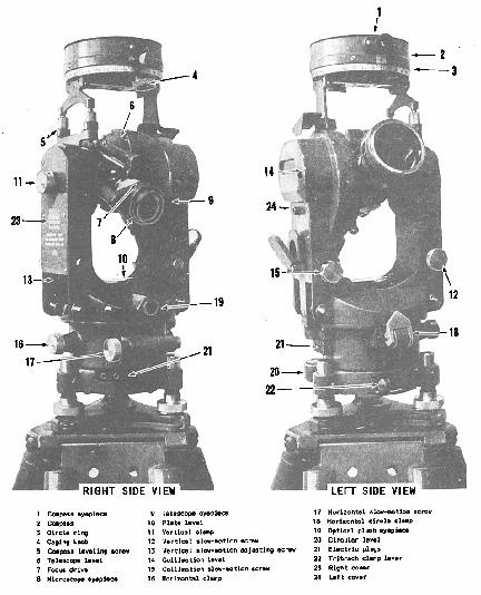
Figure 11-12.-One-minute theodolite.
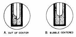
Figure
11-13.-Coincidence- type level.
shown
in figure 11-13. The TELESCOPE LEVEL,
mounted below the telescope, uses
a
prism system and a 450 mirror
for leveling operations. When the telescope is plunged to the reverse position,
the level assembly is brought to the top.
TELESCOPE.-
The
telescope of a theodolite can be rotated around the horizontal axis for direct
and reverse readings. It is a 28-power instrument with the shortest focusing
distance of about 1.4 meters. The cross wires are focused by turning the
eyepiece; the image, by turning the focusing ring. The reticle (fig. 11-14) has
horizontal and vertical cross wires, a set of vertical and horizontal ticks (at
a stadia ratio of 1:100), and a solar circle on the reticle for
making
solar observations. This circle covers 31 min of arc and can be imposed on the
sun's image (32 min of arc) to make the pointing refer to the sun'scenter.
One-half of the vertical
line
is split for finer centering on small distant objects.
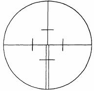
Figure 11-14.-Theodolite reticle.
The
telescope of the theodolite is an inverted image type. Its cross wires can be
illuminated by either sunlight reflected by mirrors or by battery source. The
amount of illumination for the telescope can be adjusted by changing the
position of the illumination mirror.
TRIBRACH.-
The
tribrach assembly (fig. 11-15), found on most makes and models, is a detachable
part of the theodolite that contains the leveling screw, the circular level,
and the optical plumbing device. A locking device holds the alidade and the
tribrach together and permits interchanging of instruments without moving
the
tripod. In a "leapfrog" method, the instrument (alidade) is detached
after observations are completed. It is then moved to the next station and
another tribrach. This procedure reduces the amount of instrument setup time by
half.
CIRCLES.-
The
theodolite circles are read through an optical microscope. The eyepiece is located
to the right of the telescope in the direct position, and to the left, in the
reverse. The microscope consists of a series of lenses and prisms that bring
both the horizontal and the
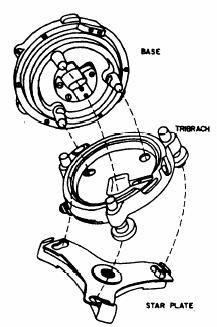
Figure
11-15.-Three-screw leveling head.
vertical
circle images into a single field of view. In the DEGREE-GRADUATED SCALES (fig.
11-16), the images of both circles are shown as they would appear through the
microscope of the 1-min theodolite. Both circles are graduated from 0 o to 360 o
with an index graduation for each degree on the main scales. This
scale'sgraduation appears to be superimposed over an auxiliary that is
graduated in minutes to cover a span of 60 min (1 o ). The position of the degree
mark on the auxiliary scale is used as an index to get a direct reading in
degrees and minutes. If necessary, these scales can be interpolated to the
nearest 0.2 min of arc.
The vertical circle
reads 0 o when the theodolite'stelescope is pointed at the zenith, and 180 o
when
it is pointed straight down. A level line reads 90 o in the direct position and
2700 in the reverse. The values read from the vertical circle are
referred to as ZENITH DISTANCES and not vertical angles. Figure 11-17 shows how
these zenith distances can be converted into vertical angles.

Figure 11-16.-Degree-graduated scales.
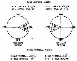
Figure
11-17.-Converting zenith distances into vertical angles (degrees).
In
the MIL-GRADUATED SCALES (fig. 11-18), the images of both circles are shown as
they would appear through the reading micro-scope of the 0.2-mil theodolite.
Both circles are graduated from 0 to 6,400 mils. The main scales are marked and
numbered every 10 mils, with the
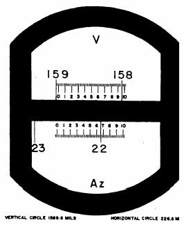
Figure 11-18.-Mil-graduated scales.
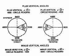
Figure 11-19.-Vertical
angles from zenith distances (mils).
last
zero dropped. The auxiliary scales are graduated from 0 to 10 roils in 0.2-mil
increments. Readings on the auxiliary scale can be interpolated to 0.1 mil. The
vertical circle reads 0 mil when the telescope is pointed at the zenith, and
3,200 mils when it is pointed straight down. A level line reads 1,600 roils in
the direct position and 4,800 roils in the reverse. The values read are zenith
distances. These zenith distances can be converted into vertical angles as
shown in figure 11-1
The
excavation of material in underwater areas is called dredging, and a dredge is
an excavator afloat on a barge. A dredge may get itself into position by cross
bearings, taken from the dredge on objects of known location on the beach, or
by some other piloting method. Many times, however, dredges are positioned by
survey triangulation. The method of determining direction angles from base line
control points is the same as that just described.
LAND SURVEYING
Land
surveying includes surveys for locating and monumenting the boundaries of a
property; preparation of a legal description of the limits of a property and of
the area included; preparation of a property map; resurveys to recover and
remonument property corners; and surveys to subdivide property. It is sometimes
necessary to retrace surveys of property lines, to reestablish lost or
obliterated corners, and to make ties to property lines and corners; for
example, a retracement survey of property lines may be required to assure that
the military operation of quarry excavation does not encroach on adjacent
property where excavation rights have not been obtained. Similarly, an access
road from a public highway to the quarry site, if it crosses privately owned
property, should be tied to the property lines that are crossed so that
correctly executed easements can be obtained to cross the tracts of private
property.
EAs may be required to accomplish property surveys
at naval activities outside the continental limits of the United States for the
construction of naval bases and the restoration of such properties to property
owners. The essentials of land surveying as practiced in various countries are
similar in principle. Although the principles pertaining to the surveys of
public and private lands within the United States are not necessarily directly
applicable to foreign countries, a knowledge of these principles will enable
the EA to conduct the survey in a manner required by the property laws of the
nation concerned.
In the United States, land surveying is a survey
conducted for the purpose of ascertaining the correct boundaries of real estate
property for legal purposes. In accordance with federal and states laws, the
right and/or title to landed property in the United States can be transferred
from one person to another only by means of a written document, commonly called
a deed. To constitute a valid transfer, a deed must meet a considerable number
of legal requirements, some of which vary in different states. In all the
states, however, a deed must contain an accurate description of the boundaries
of the property.
A
right in real property need not be complete, outright ownership (called fee
simple). There are numerous lesser rights, such as leasehold (right to
occupancy and use for a specified term) or easement (right to make certain
specified use of property belonging to someone else). But in any case, a valid
transfer of any type of right in real property usually involves an accurate
description of the boundaries of the property.
As
mentioned previously, the EA may be required to perform various land surveys.
As a survey team or crew leader, you should have a knowledge of the principles
of land surveys in order to plan your work accordingly.
PROPERTY BOUNDARY
DESCRIPTION
A parcel of land may be described by
metes and bounds, by giving the coordinates of the property corners with
reference to the plane coordinates system, by a deed reference to a description
in a previously recorded deed, or by References to block and individual
property numbers appearing on a recorded map.
By
Metes and Bounds
When a tract of land is defined by
giving the bearings and lengths of all boundaries, it is said to be described
by metes and bounds. This is an age-old method of describing land that still
forms the basis for the majority of deed descriptions in the eastern states of
the United States and in many foreign lands. A good metes-and-bounds description
starts at a point of beginning that should be monumented and referenced by ties
or distances from well-established monuments or other reference points. The
bearing and length of each side is given, in turn, around the tract to close
back on the point of beginning. Bearing may be true or magnetic grid,
preferably the former. When magnetic bearings are read, the declination of the
needle and the date of the survey should be stated. The stakes or monuments
placed at each corner should be described to aid in their recovery in the
future. Ties from corner monuments to witness points (trees, poles, boulders,
ledges, or other semipermanent or permanent objects) are always helpful in
relocating corners, particularly where the corner markers themselves lack permanence.
In timbered country, blazes on trees on or adjacent to a boundary line are most
useful in reestablishing the line at a future date. It is also advisable to
state the names of abutting property owners along the several sides of the
tract being described. Many metes-and-bounds descriptions fail to include all
of these particulars and are frequently very difficult to retrace or locate in
relation to adjoining ownerships.
One of the reasons why the determination
of boundaries in the United States is often difficult is that early surveyors
often confined themselves to minimal description; that is, to a bare statement
of the metes metesToday, good practice requires that a land surveyor include
all relevant information in his description.
In preparing the description of a
property, the surveyor should bear in mind that the description must clearly
identify the location of the property and must give all necessary data from
which the boundaries can be reestablished at any future date. The written
description contains the greater part of the information shown on the plan.
Usually both a description and a plan are prepared and, when the property is
transferred, are recorded according to the laws of the county concerned. The
metes-and-bounds description of the property shown in figure 10-34 is given
below.
"All that certain tract or parcel
of land and premises, hereinafter particularly described, situate, lying and
being in the Township of Maplewood in the County of Essex and State of New
Jersey and constituting lot 2 shown on the revised map of the Taylor property
in said township as filed in the Essex County Hall of Records on March 18,
1944.
"Beginning at an iron pipe in the
northwesterly line of Maplewood Avenue therein distant along same line four
hundred and thirty-one feet and seventy- one-hundredths of a foot
north-easterly from a stone monument at the northerly corner of Beach Place and
Maplewood Avenue; thence running (1) North forty-four degrees thirty-one and
one-half minutes West along land of. . ."
Another form of a lot
description maybe presented as follows:
"Beginning at the northeasterly corner of the
tract herein described; said corner being the intersection of the southerly
line of Trenton Street and the westerly line of Ives Street; thence running
S6 o 29�54��E bounded easterly by said Ives Street, a distance of two hundred and
twenty-seven one hundredths (200.27) feet to the northerly line of Wickenden
Street; thence turning an interior angle of 89 o 59�16�� and run-ning
S83 o 39�50��W bonded southerly by said Wickenden Street, a distance of one
hundred and no one-hundredths (100.00) feet to a corner; thence turn-ing an
interior angle of. . . ."
You
will notice that in the above example, interior angles were added to the
bearings of the boundary lines. This will be another help in retracing lines
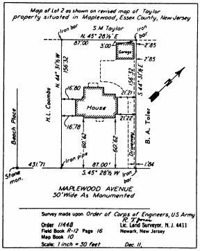
Figure 10-34.-Lot plan
by metes and bounds.
INTRO TO ANTIQUE SURVEY
INSTRUMENTS
First,
some basics about their composition and finish... most instruments were made of
wood, brass, or aluminum, although you will find whole instruments or
instrument parts made of iron, steel, ebony, ivory, celluloid, and plastic. It
is important to remember that many surveying instruments were
"needle" instruments and their magnetic needles would not seek north
properly if there were local sources of interference, such as iron. The United
States General Land Office issued instructions requiring brass Gunters chains
to be used in close proximity to the magnetic needle. (They soon changed that
requirement to steel brazed link chains; the brass chain could not stand up to
the type of wear and tear a chain received.
In American surveying instruments, wood
was common until about 1800; brass instruments were made approximately 1775 to
1975, and aluminum instruments from 1885 to the present.
The finish of instruments has changed.
Early wooden instruments were generally unfinished and were usually made of
tight grained woods which resisted water well. Early brass instruments were
usually unfinished or polished and lacquered to retain the shine. In the
mid-1800s American instrument makers began finishing brass instruments with
dark finishes for two reasons: first, that the dark finish reduced glare and as
a result reduced eyestrain, and secondly, that the dark finish helped to even
out the heating of an instrument in the sunlight and as a result reduced
collimation problems caused by the heating. Beware of being taken in by
polished and lacquered brass instruments; prior to 1900 that may have been the
original finish for the instrument, but after 1900 , bright brass finishes are
usually not original finishes.
There are three kinds of surveying
instruments that are rather unique to North American surveying. They are the
compass, the chain and the transit. In addition, the engineer's or surveyor's
level contributed very strongly to making the United States the leading
industrial nation in the world by virtue of the highly efficient railroad
systems it helped design in the mid 1800's. I take a great deal of satisfaction
in pointing out that in this country it was the compass and chain that won the
west, not the six-shooter!
The following is a list of antique
surveying instruments and tools with a brief and basic description of how they
were used.
ABNEY
HAND LEVEL - Measures vertical angles.
ALIDADE
- Used on a Plane Table to measure vertical and horizontal angles &
distances.
ALTAAZIMUTH INSTRUMENT - Measures
horizontal and vertical angles; for position "fixing".
ASTRONOMIC TRANSITS - Measures vertical
angles of heavenly bodies; for determining geographic position.
BAROMETER,
ANEROID - Measures elevations; used to determine vertical distance.
BASE-LINE
BAR - Measures horizontal distances in triangulation and trilateration surveys.
BOX
SEXTANT - Measures vertical angles to heavenly bodies.
CHRONOGRAPH
- Measures time.
CHRONOMETER
- Measures time.
CIRCUMFERENTER
- Measures horizontal directions and angles.
CLINOMETER
- Measures vertical angles.
COLLIMATOR
- For adjusting and calibrating instruments.
COMPASSES
- Determines magnetic directions; there are many kinds, including plane,
vernier, solar, telescopic, box, trough, wet, dry, mariners, prismatic, pocket,
etc.
CROSS, SURVEYORS - For
laying out 90 and 45 degree angles.
CURRENT METER -
Measures rate of water flow in streams and rivers.
DIAL,
MINER'S - A theodolite adapted for underground surveying; measures directions
as well as horizontal and vertical angles.
GONIOMETER - Measures
horizontal and vertical angles.
GRADIOMETER
- Also known as Gradiometer level, it measures slight inclines and level
lines-of-sight.
HELIOGRAPH - Signalling
device used in triangulation surveys.
HELIOSTAT
- Also known as a heliotrope, it was used to make survey points visible at long
distances, particularly in triangulation surveys.
HORIZON, ARTIFICIAL -
Assists in establishing a level line of sight, or "horizon".
HYPSOMETER
- Used to estimate elevations in mountainous areas by measuring the boiling
points of liquids. This name was also given to an instrument which determined
the heights of trees.
INCLINOMETER - Measures
slopes and/or vertical angles.
LEVEL
- Measures vertical distances (elevations). There are many kinds, including
Cooke's, Cushing's, Gravatt. dumpy, hand or pocket, wye, architect's, builder's,
combination, water, engineer's, etc.
LEVELLING ROD - A tool
used in conjunction with a levelling instrument.
LEVELLING STAVES - Used
in measuring vertical distances.
MINER'S COMPASS -
Determines magnetic direction; also locates ore.
MINER'S PLUMMET - A
"lighted" plumb bob, used in underground surveying.
MINING
SURVEY LAMP - Used in underground surveying for vertical and horizontal
alignment.
OCTANT - For measuring
the angular relationship between two objects.
PEDOMETER - Measures
paces for estimating distances.
PERAMBULATOR - A wheel
for measuring horizontal distances.
PHOTO-THEODOLITE
- Determines horizontal and vertical positions through the use of
"controlled" photographs.
PLANE TABLE - A survey
drafting board for map-making with an alidade.
PLUMB BOB - For
alignment; hundreds of varieties and sizes.
PLUMMETS - Same as
plumb bob.
QUADRANT - For
measuring the angular relationship between two objects.
RANGE POLES - For
vertical alignment and extending straight lines.
SEMICIRCUMFERENTER -
Measures magnetic directions and horizontal angles.
SEXTANTS
- Measures vertical angles; there are many kinds, including box, continuous
arc, sounding, surveying, etc.
SIGNAL MIRRORS - For
communicating over long distances; used in triangulation surveys.
STADIA BOARDS - For
measuring distances; also known as stadia rods.
STADIMETER or
STADIOMETER - For measuring distances.
TACHEOMETER
- A form of theodolite that measures horizontal and vertical angles, as well as
distances.
TAPES
- For measuring distances; made of many materials, including steel, invar,
linen, etc. Also made in many styles, varieties, lengths, and increments.
THEODOLITE
- Measures horizontal and vertical angles. Its name is one of the most misused
in surveying instrument nomenclature, and is used on instruments that not only
measure angles, but also directions and distances. There are many kinds,
including transit, direction, optical, solar, astronomic, etc.
TRANSIT
- For measuring straight lines. Like the theodolite, the transit's name is
often misused in defining surveying instruments. Most transits were made to
measure horizontal and vertical angles and magnetic and true directions. There
are many kinds, including astronomic, solar, optical, vernier, compass, etc.
WAYWISER - A wheel for
measuring distances
Related Topics