Chapter: Civil : Foundation Engineering : Site Investigation And Selection Of Foundation
Site Investigation And Selection Of Foundation

SITE INVESTIGATION AND
SELECTION OF FOUNDATION
Types of boring
1.Displacement borings
It is combined method of sampling & boring
operation. Closed bottom sampler, slit cup, or piston type is forced in to the
ground up to the desired depth. Then the sampler is detached from soil below
it, by rotating the piston, & finally the piston is released or withdrawn.
The sampler is then again forced further down & sample is taken. After
withdrawal of sampler & removal of sample from sampler, the sampler is kept
in closed condition & again used for another depth.
Features
:
� Simple
and economic method if excessive caving does not occur. Therefore not suitable
for loose sand.
� Major
changes of soil character can be detected by means of penetration resistance.
� These
are 25mm to 75mm holes.
� It
requires fairly continuous sampling in stiff and dense soil, either to protect
the sampler from damage or to avoid objectionably heavy construction pit.
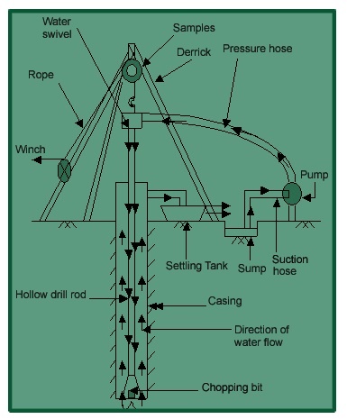
2.Wash boring:
It is a popular method due to the use of limited
equipments. The advantage of this is the use of inexpensive and easily portable
handling and drilling equipments. Here first an open hole is formed on the
ground so that the soil sampling or rock drilling operation can be done below
the hole. The hole is advanced by chopping and twisting action of the light
bit. Cutting is done by forced water and water jet under pressure through the
rods operated inside the hole.
In India the 'Dheki' operation is used, i.e.using,
horizontal lever arrangement and by the process of suction and application of
pressure, soil slurry comes out of the tube and pipe goes down. This can be
done upto a depth of 8m -10m (excluding the depth of hole already formed
beforehand)
Just
by noting the change of colour of soil coming out with the change of soil
character can be identified by any experienced person. It gives completely
disturbed sample and is not suitable for very soft soil, fine to medium grained
cohesionless soil and in cemented soil.
1.1Planning For Subsurface
Exploration
The planning of the site exploration program
involves location and depth of borings, test pits or other methods to be used,
and methods of sampling and tests to be carried out. The purpose of the
exploration program is to determine, within practical limits, the
stratification and engineering properties of the soils underlying the site. The
principal properties of interest will be the strength, deformation, and
hydraulic characteristics. The program should be planned so that the maximum
amount of information can be obtained at minimum cost. In the earlier stages of
an investigation, the information available is often inadequate to allow a firm
and detailed plan to be made. The investigation is therefore performed in the
following phases:
1.Fact
finding and geological survey
Reconnaissance
1. Preliminary
exploration
2.Detailed
exploration
1.Fact finding and geological survey
Assemble all information on dimensions, column
spacing, type and use of structure, basement requirements, and any special
architectural considerations of the proposed building. Foundation regulations
in the local building code should be consulted for any special requirements.
For bridges the soil engineer should have access to type and span lengths as
well as pier loadings. This information will indicate any settlement
limitations, and can be used to estimate foundation loads.
2.Reconnaissance
This may be in the form of a field trip to the site
which can reveal information on the type and behavior of adjacent sites and
structures such as cracks, noticeable sags, and possibly sticking doors and
windows. The type of local existing structure may influence, to a considerable
extent, the exploration program and the best foundation type for the proposed
adjacent structure. Since nearby existing structures must be maintained,
excavations or vibrations will have to be carefully controlled. Erosion in existing
cuts (or ditches) may also be observed. For highways, run off patterns , as
well as soil stratification to the depth of the erosion cut , may be observed.
Rock outcrops may give an indication of the presence or the depth of bedrock.
3.Auger boring
This method is fast and economical, using simple,
light, flexible and inexpensive instruments for large to small holes. It is
very suitable for soft to stiff cohesive soils and also can be used to
determine ground water table. Soil removed by this is disturbed but it is
better than wash boring, percussion or rotary drilling. It is not suitable for
very hard or cemented soils, very soft soils, as then the flow into the hole
can occur and also for fully saturated cohesionless soil.
3.Auger boring
This method is fast and economical, using simple,
light, flexible and inexpensive instruments for large to small holes. It is
very suitable for soft to stiff cohesive soils and also can be used to
determine ground water table. Soil removed by this is disturbed but it is
better than wash boring, percussion or rotary drilling. It is not suitable for
very hard or cemented soils, very soft soils, as then the flow into the hole
can occur and also for fully saturated cohesionless soil. Soil Sampling
In
general soil samples are categorized as shown in fig. 1.5
Fig.
1.5 Types of samples
Disturbed
samples:
The structure of the soil is disturbed to the
considerable degree by the action of the boring tools or the excavation
equipments.
The
disturbances can be classified in following basic types:
Change
in the stress condition,
Change
in the water content an
Disturbed
samples:
The structure of the soil is disturbed to the
considerable degree by the action of the boring tools or the excavation
equipments.
The
disturbances can be classified in following basic types:
Change
in the stress condition,
Change
in the water content and the void ratio,
Disturbance
of the soil structure,
Chemical changes,
Mixing and segregation of soil constituents
The causes of the disturbances are listed below:
Method of advancing the borehole,
Mechanism used to advance the sampler,
Dimension and type of sampler,
Procedure followed in
sampling and boring. Undisturbed samples: It retains as closely as
practicable the true insitu structure and water content of the soil. For
undisturbed sample the stress changes can not be avoided. The following
requirements are looked for:
No change due to disturbance of the soil structure,
No change in void ratio and water content,
No
change in constituents and chemical properties.
4
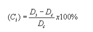
Requirement of good sampling process : Inside clearance
ratio The soil is under great stress as it enters the sampler and has a
tendency to laterally expand. The inside clearance should be large enough to
allow a part of lateral expansion to take place, but it should not be so large
that it permits excessive deformations and causes disturbances of the sample.
For good sampling process, the inside clearance ratio should be within 0.5 to 3
%. For sands silts and clays, the ratio should be 0.5 % and for stiff and hard
clays (below water table), it should be 1.5 %.
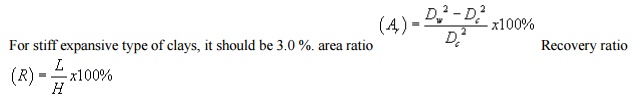
Where, L is the length of the sample within the
tube,
H is the depth of penetration of the sampling tube.
It represents the disturbance of the soil sample.
For good sampling the recovery ratio should be 96 to 98 %.
Wall friction can be reduced by suitableinside
clearance, smooth finish and oiling.
The non-returned wall should have large orifice to allow air and water to escape. In-situ tests General The in situ tests in the field have the advantage of testing the soils in their natural, undisturbed condition. Laboratory tests, on the other hand, make use of small size samples obtained from boreholes through samplers and therefore the reliability of these depends on the quality of the so cal samples from non-cohesive, granular soils is not easy, if not impossible. Therefore, it is common practice to rely more on laboratory tests where cohesive soils are concerned. Further, in such soils, the field tests being short duration tests, fail to yield meaningful consolidation settlement data in any case. Where the subsoil strata are essentially non-cohesive in character, the bias is most definitely towards field tests. The data from field tests is used in empirical, but time-tested correlations to predict settlement of foundations. The field tests commonly used in subsurface investigation are:
Penetrometer
test
Pressuremeter
test
Vane
shear testPlate load test
Geophysical
methods ![]()
Penetrometer Tests :
Standard
penetration test (SPT)
Static
cone penetration test (CPT)
Dynamic
cone penetration test (DCPT) Standard
penetration test
The standard
penetration test is carried out in a borehole, while the DCPT and SCPT are
carried out without a borehole. All the three tests measure the resistance of
the soil strata to penetration by a penetrometer. Useful empirical correlations
between penetration resistance and soil properties are available for use in
foundation design.
This is the most
extensively used penetrometer test and employs a split-spoon sampler, which
consists of a driving shoe, a split-barrel of circular cross-section which is
longitudinally split into two parts and a coupling. IS: 2131-1981 gives the
standard for carrying out the test.
Procedure
1. The
borehole is advanced to the required depth and the bottom cleaned.
2. The
split-spoon sampler, attached to standard drill rods of required length is
lowered into the borehole and rested at the bottom
3. The
split-spoon sampler is driven into the soil for a distance of 450mm by blows of
a drop hammer (monkey) of 65 kg falling vertically and freely from a height of
750 mm. The number of blows required to penetrate every 150 mm is recorded
while driving the sampler. The number of blows required for the last 300 mm of
penetration is added together and recorded as the N value at that particular
depth of the borehole. The number of blows required to effect the first 150mm
of penetration, called the seating drive, is disregarded. The split-spoon
sampler is then withdrawn and is detached from the drill rods. The split-barrel
is disconnected from the cutting shoe and the coupling. The soil sample
collected inside the split barrel is carefully collected so as to preserve the natural moisture content and
transported to the laboratory for tests. Sometimes, a thin liner is inserted
within the split-barrel so that at the end of the SPT, the liner containing the
soil sample is sealed with molten wax at both its ends before it is taken away
to the laboratory. The SPT is carried out at every 0.75 m vertical intervals in
a borehole. This can be increased to 1.50 m if the depth of borehole is large.
Due to the presence of boulders or rocks, it may not be possible to drive the
sampler to a distance of 450 mm. In such a case, the N value can be recorded
for the first 300 mm penetration. The boring log shows refusal and the test is
halted if
50
blows are required for any 150mm penetration
100
blows are required for 300m penetration
10 successive blows produce no advance.
v Precautions
The
drill rods should be of standard specification and should not be in bent
condition.
The
split spoon sampler must be in good condition and the cutting shoe must be free
from wear and tear.
The drop hammer must be of the right
weight and the fall should be free, frictionless and vertical. The SPT is
carried out at every 0.75 m vertical intervals in a borehole. This can be
increased to 1.50 m if the depth of borehole is large. Due to the presence of
boulders or rocks, it may not be possible to drive the sampler to a distance of
450 mm. In such a case, the N value can be recorded for the first 300 mm
penetration. The boring log shows refusal and the test is halted if
50
blows are required for any 150mm penetration
100
blows are required for 300m penetration ![]() 10 successive blows produce no
advance.
10 successive blows produce no
advance.
v
Precautions
The drill rods should be of standard specification
and should not be in bent condition.
The split spoon sampler must be in good condition
and the cutting shoe must be free from wear and tear.
The drop hammer must be
of the right weight and the fall should be free, frictionless and vertical. The
height of fall must be exactly 750 mm. Any change from this will seriously
affect the N value.
The bottom of the
borehole must be properly cleaned before the test is carried out. If this is
not done, the test gets carried out in the loose, disturbed soil and not in the
undisturbed soil. When a casing is used in borehole, it should be ensured that
the casing is driven just short of the level at which the SPT is to be carried
out. Otherwise, the test gets carried out in a soil plug enclosed at the bottom
of the casing.
When the test is
carried out in a sandy soil below the water table, it must be ensured that the
water level in the borehole is always maintained slightly above the ground
water level. If the water level in the borehole is lower than the ground water
level, 'quick' condition may
develop in the recorded. In spite of all these
imperfections, SPT is still extensively used because ![]() the test is simple and relatively
economical.
the test is simple and relatively
economical.
it is the only test
that provides representative soil samples both for visual inspection in the
field and for natural moisture content and classification tests in the
laboratory. SPT values obtained in the field for sand have to be corrected
before they are used in empirical correlations and design charts. IS: 2131-1981
recommends that the field value of N be corrected for two effects, namely, (a)
effect of overburden pressure, and (b) effect of dilatancy. (a) Correction for
overburden pressure
Several investigators
have found that the penetration resistance or the N value in a granular soil is
influenced by the overburden pressure. Of two granular soils possessing the
same relative density but having different confining pressures, the one with a
higher confining pressure gives a higher N value. Since the confining pressure
(which is directly proportional to the overburden pressure) increases with
depth, the N values at shallow depths are underestimated and the N values at
larger depths are overestimated. To allow for this, N values recorded from
field tests at different effective overburden pressures are corrected to a
standard effective overburden pressure.
Static cone
penetration test At field SCPT is widely used of
recording variation in the in-situ penetration resistance of soil in
cases where in-situ density is disturbed by boring method & SPT is
unreliable below water table. The test is very useful for soft clays, soft
silts, medium sands & fine sands.
Procedure
By this test basically
by pushing the standard cone at the rate of 10 to 20 mm/sec in to the soil and
noting the friction, the strength is determined.
After installing the
equipment as per IS-4968, part III the sounding rod is pushed in to the soil
and the driving is operated at the steady rate of 10 mm/sec approximately so as
to advance the cone only by external loading to the depth which a cone assembly
available.
For finding combine
cone friction resistance, the shearing strength of the soil qs , and
tip resistance qc is noted in gauge & added to get the total
strength
LimitationsThis
test is unsuitable for gravelly soil & soil for having SPT N value greater
than 50. Also in dense sand anchorage becomes to cumbersome &
expensive & for such cases Dynamic SPT can be used. This test is also
unsuitable for field operation since erroneous value obtained due to presence
of brick bats, loose stones etc.
Geophysical exploration
General Overview Geophysical exploration may be used with
advantage to locate boundaries between different elements of the subsoil
as these procedures are based on the fact that the gravitational, magnetic,
electrical, radioactive or elastic properties of the different elements of the
subsoil may be different. Differences in the gravitational, magnetic and
radioactive properties of deposits near the surface of the earth are seldom
large enough to permit the use of these properties in exploration work for
civil engineering projects. However, the resistivity method based on the electrical
properties and the seismic refraction method based on the elastic properties of
the deposits have been used widely in large civil engineering projects.
Different methods of geophysical
explorations 1 Electrical resistivity method:
Electrical
resistivity method is based on the difference in the electrical conductivity or
the electrical resistivity of different soils. Resistivity is defined as
resistance in ohms between the opposite phases of a unit cube of a material.
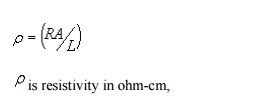
R is resistance in ohms,
A is the cross sectional area (cm 2),
L is length of the conductor (cm).
The resistivity values of the different soils
are listed in table 1.4
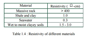
Material Resistivity
( -cm)
Massive rock > 400
Shale and clay 1.0
Seawater 0.3
Wet to moist clayey
soils 1.5 - 3.0
Table
1.4 : Resistivity of different materials
v Procedure
The
set up for the test is given in figure 1.13. In this method, the electrodes are
driven approximately 20cms in to the ground and a dc or a very low frequency ac
current of known magnitude is passed between the outer (current) electrodes,
thereby producing within the soil an electrical field and the boundary
conditions. The electrical potential at point C is Vc and at point D
is V d which is measured by means of the inner (potential)
electrodes respectively.
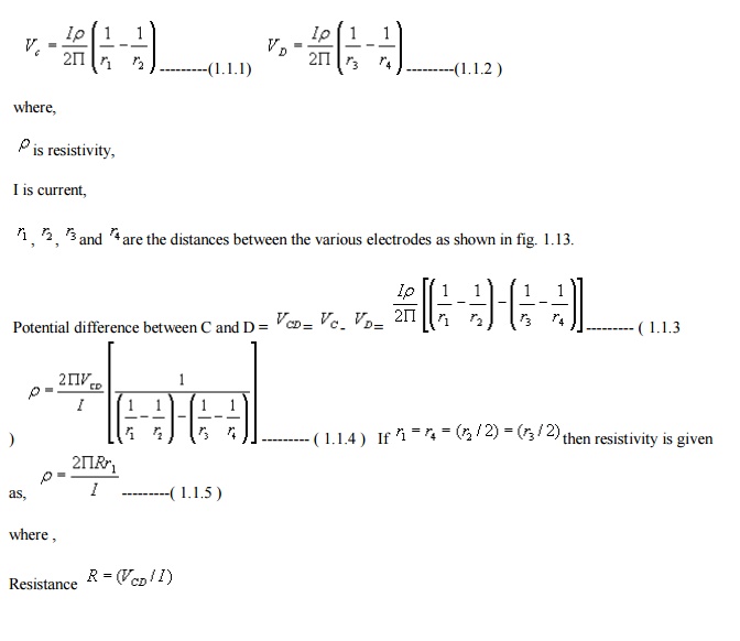
Thus, the apparent resistivity of the soil to a
depth
approximately equal to
the spacing of the electrode can be computed. The resistivity unit is often so
designed that the apparent resistivity can be read directly on the
potentiometer.
In 'resistivity
mapping' or 'transverse profiling their spacing, and the apparent resistivity
and any anomalies within a depth equal to the spacing of the electrodes
can thereby be determined for a number of points.
approximately equal to
the spacing of the electrode can be computed. The resistivity unit is often so
designed that the apparent resistivity can be read directly on the
potentiometer.
In
'resistivityapping'orm 'transverse profiling' the elect their spacing, and the
apparent resistivity and any anomalies within a depth equal to the spacing of
the electrodes
can thereby be determined for a number of points.
Seismic
refraction method General This method is based on the fact
that seismic waves have different velocities in different types of soils
(or rock) and besides the wave refract when they cross boundaries between
different types of soils. In this method, an artificial impulse are produced
either by detonation of explosive or mechanical blow with a heavy hammer at
ground surface or at the shallow depth within a hole. These shocks generate
three types of waves. Longitudinal or compressive wave or primary (p) wave,
Transverse or shear waves or secondary (s) wave, Surface waves.
It
is primarily the velocity of longitudinal or the compression waves which is
utilized in this method. The equation for the velocity of the p-waves and
s-waves is given as,
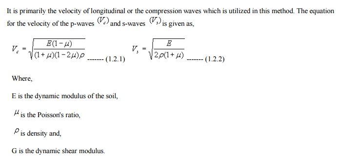
G is the dynamic shear modulus.
v These waves are
classified as direct, reflected and refracted waves. The direct wave travel in
approximately straight line from the source of impulse. The reflected and
refracted wave undergoes a change in direction when they encounter a boundary
separating media of different seismic velocities (Refer fig. 1.19). This method
is more suited to the shallow explorations for civil engineering purpose. The
time required for the impulse to travel from the shot point to various points
on the ground surface is determined by means of geophones which transform the
vibrations into electrical currents and transmit them to a recording unit or
oscillograph, equipped with a timing mechanism. Assumptionshyj
METHODS OF ANALYSIS
LIMIT EQUILIBRIUM
The so-called limit equilibrium
method has traditionally being used to obtain approximate solutions for the
stability problems in soil mechanics. The method entails a assumed failure
surface of various simple shapes-plane, circular, log spiral. With this
assumption, each of the stability problems is reduced to one of finding the
most dangerous position of the failure or slip surface of the shape chosen
which may not be particularly well founded, but quite often gives acceptable
results. In this method it is also necessary to make certain assumptions
regarding the stress distribution along the failure surface such that the
overall equation of equilibrium, in terms of stress resultants, may be written
for a given problem. Therefore, this simplified method is used to solve various
problems by simple statics.
Although the limit equilibrium technique utilizes
the basic concept of upper-bound rules.
Of Limit Analysis, that
is, a failure surface is assumed and a least answer is sought, it does not meet
the precise requirements of upper bound rules, so it is not a upper bound. The
method basically gives no consideration to soil kinematics, and equilibrium
conditions are satisfied in a limited sense. It is clear then that a solution
obtained using limit equilibrium method is not necessarily upper or lower
bound. However, any upper-bound limit analysis solution will be obviously limit
equilibrium solution.
INTRODUCTION
Partly for the
simplicity in practice and partly because of the historical development of
deformable of solids, the problems of soil mechanics are often divided into two
distinct groups -the stability problems and elasticity problems. The stability
problems deal with the conditions of ultimate failure of mass of soil. Problems
of earth pressure, bearing capacity, and stability of slopes most often are
considered in this category. The most important feature of such problems is the
determination of the loads which will cause the failure of the soil mass.
Solutions of these problems are done using the theory of perfect elasticity.
The elasticity problems on the other hand deal with the stress or deformation
of the soil where no failure of soil mass is involved. Stresses at points in a
soil mass under the footing, or behind a retaining wall, deformation around
tunnels or excavations, and all settlement problems belong to this category.
Solutions to these problems are obtained by using the theory of linear
elasticity.
Intermediate between
the elasticity and stability problems are the problems mentioned above are the
problems known as progressive failure. Progressive failure problems deal
with the elastic- plastic transition from the initial linear elastic state to
the ultimate failure state of the soil by plastic flow. The following section
describes some of the methods of analysis which are unique with respect to each
other.
DIFFERENT METHODS OF
ANALYSIS
There are basically four methods of analysis:
![]()
Limit
Equilibrium.
![]() Limit Analysis.
Limit Analysis.
![]() Method of
Characteristics.
Method of
Characteristics.
![]()
Finite
Element / Discrete Element Method. THEOREMS
There are two theorems
which are used for the various analyses. Some follow one theorem while some
methods of analysis follow the other. They are the upper bound and the lower
bound theorems.
In the Upper bound
theorem , loads are determined by equating the external work to the
internal work in an assumed deformation mode that satisfies:
Boundary deformation pattern.
Strain and velocity compatibility conditions.
These are kinematically admissible solutions. This
analysis gives the maximum value for a particular parameter.
In the Lower bound theorem , loads are
determined from the stress distribution that satisfies:
Stress equilibrium conditions.
Stress boundary conditions.
Nowhere it violates the yield condition.
These are statically admissible solutions. This
analysis gives the minimum value for a particular parameter.
However
by assuming different failure surfaces the difference between the values
obtained the upper and lower bound theorems can be minimized.
Related Topics