Chapter: Flexible Alternating Current Transmission System : Thyristor Controlled Series Capacitor (TCSC) and Applications
Operaton of TCSC(Thyristor Controlled Series Capacitor)
OPERATON
OF TCSC
1. Basic
Principle
Ø A TCSC is
a series-controlled capacitive reactance that can provide continuous
Ø control
of power on the ac line over a wide range.
Ø The
principle of variable-series compensation is simply to increase the
fundamental-frequency voltage across an fixed capacitor (FC) in a series
compensated line through appropriate variation of the firing angle.
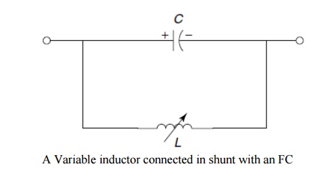
Ø This
enhanced voltage changes the effective value of the series-capacitive
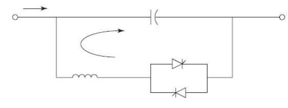
reactance. A simple understanding of TCSC functioning can be obtained by
analyzing the behavior of a variable inductor connected in parallel with an FC,
as shown in Fig.
Ø The
equivalent impedance, Zeq, of this LC combination is expressed as
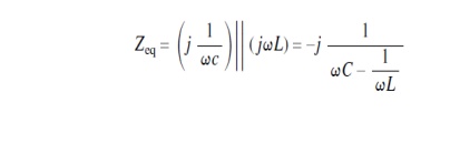
Ø The
impedance of the FC alone, however, is given by −j(1/ ωC).
Ø If ωC−(1/ ωL) > 0 or, in other words, ωL
> (1/ ωC), the reactance of the FC
is less than that of the parallel-connected variable reactor and that this
combination provides a variable-capacitive reactance are both implied.
Moreover, this inductor increases the equivalent-capacitive reactance of the LC combination above that of the FC.
Ø If ωC − (1/ ωL) c 0, a resonance develops that results in an infinite-capacitive
impedance is obviously unacceptable condition.
Ø If,
however, ωC − (1/ ωL) < 0, the LC combination provides inductance above the value of the fixed
inductor. This situation corresponds to the inductive-vernier mode of the TCSC
operation.
Ø In the
variable-capacitance mode of the TCSC, as the inductive reactance of the
variable inductor is increased, the equivalent-capacitive eactance is gradually
decreased.
Ø The
minimum equivalent-capacitive reactance is obtained for extremely large
inductive reactance or when the variable inductor is open-circuited, in which
the value is equal to the reactance of the FC itself.
Ø The
behavior of the TCSC is similar to that of the parallel LC combination.
Ø The
difference is that the LC-combination
analysis is based on the presence of pure sinusoidal voltage and current in the
circuit, whereas in the TCSC, because of the voltage and current in the FC and
thyristor-controlled reactor (TCR) are not sinusoidal because of thyristor
switchings.
2. DIFFERENT MODES OF OPERATION
1. Bypassed Thyristor mode:
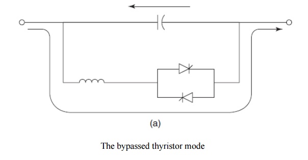
Ø In this
bypassed mode, the thyristors are made to fully conduct with a conduction angle
of 180. Gate pulses are applied as soon as the voltage across the
thyristors reaches zero and becomes positive, resulting in a continuous sinusoidal
of flow current through the thyristor valves.
Ø The TCSC
module behaves like a parallel capacitor–inductor combination. However, the net
current through the module is inductive, for the susceptance of the reactor is
chosen to be greater than that of the capacitor.
Ø Also
known as the thyristor-switched-reactor
(TSR) mode, the bypassed thyristor mode is distinct from the bypassed-breaker mode, in which the
circuit breaker provided across the series capacitor is closed to remove the
capacitor or the TCSC module in the event of TCSC faults or transient over
voltages across the TCSC.
Ø This mode
is employed for control purposes and also for initiating certain protective
functions.
Ø Whenever
a TCSC module is bypassed from the violation of the current limit, a
finite-time delay, T delay, must
elapse before the module can be reinserted after the line current falls below
the specified limit.
2.Blocked – Thyristor Mode:
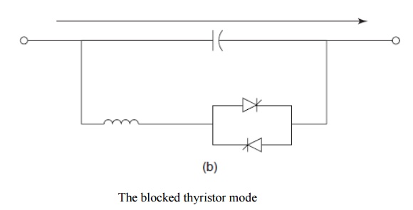
Ø In this
mode, also known as the waiting mode,
the firing pulses to the thyristor valves are blocked.
Ø If the
thyristors are conducting and a blocking command is given, the thyristors turn
off as soon as the current through them reaches a zero crossing.
Ø The TCSC
module is thus reduced to a fixed-series capacitor, and the net TCSC reactance
is capacitive.
Ø In this
mode, the dc-offset voltages of the capacitors are monitored and quickly
discharged using a dc-offset control [9] without causing any harm to the
transmission-system transformers.
3 Partially Conducting Thyristor Mode or
Vernier Mode:
Ø This mode
allows the TCSC to behave either as a continuously controllable capacitive
reactance or as a continuously controllable inductive reactance.
Ø It is
achieved by varying the thyristor-pair firing angle in an appropriate range.
However, a smooth transition from the capacitive to inductive mode is not
permitted because of the resonant region between the two modes.
Ø A variant
of this mode is the capacitive-vernier-control
mode, in which the thyristors are fired when the capacitor voltage and
capacitor current have opposite polarity.
Ø This
condition causes a TCR current that has a direction opposite that of the
capacitor current, thereby resulting in a loop-current flow in the TCSC
controller.
Ø The loop
current increases the voltage across the FC, effectively enhancing the
equivalent-capacitive reactance and the series-compensation level for the same
value of line current.
Ø To
preclude resonance, the firing angle α of the forward-facing thyristor, as
measured from the positive reaching a zero crossing of the capacitor voltage,
is constrained in the range α min ≤ α ≤ 1800.
Ø This
constraint provides a continuous vernier control of the TCSC module reactance.
The loop current increases as α is decreased from 1800 to α min.
Ø The
maximum TCSC reactance permissible with a c α min is typically two-and-a-half
to three times the capacitor reactance at fundamental frequency.
Ø Another
variant is the inductive-vernier mode,
in which the TCSC can be operated by having a high level of thyristor
conduction.
Ø In this
mode, the direction of the circulating current is reversed and the controller
presents a net inductive impedance.
Ø Based on
the three modes of thyristor-valve operation, two variants of the TCSC emerge:
1. Thyristor-switched
series capacitor (TSSC), which permits a discrete control of
the capacitive reactance.
2. Thyristor-controlled
series capacitor (TCSC), which offers a continuous control
of capacitive or inductive reactance.
Related Topics