Chapter: Power Quality : Over Voltages
Mitigation of voltage swells
Mitigation of voltage swells:
Over voltages are extremely transient phenomena
occurring for only fractions of a second, but which can never less have a
negative effect on electronic equipment and can even result in their total
failure. The total losses are due not only to the hardware damage and resultant
repair costs, but above all to the major consequential costs due to stoppages
in health facilities offices and production plants.
Although damage due to over voltage primarily
occurs in industry and large community and office complexes, the losses
suffered in the private sector due to damaged video, TV equipment and personal
computers have also reached considerable levels. Over voltage protection units
such as surge arresters and other protective systems can be installed at low
cost in relation to the potential losses, so it makes economic sense to install
such equipment.
The basic
principles of over voltage protection of load equipments are:
├╝ Limit the
voltage across sensitive insulation
├╝ Divert
the surge current away from the load
├╝ Block the
surge current entering into the load
├╝ Bonding
of equipment with ground
├╝ Prevent
surge current flowing between grounds
├╝ Design a
low pass filter using limiting and blocking principle.
1. Surge Arresters and Surge
Suppressors:
A surge arrester is a protective device for limiting surge voltages on equipment by discharging or bypassing surge current. Surge arrester allows only minimal flow of the 50 Hz/60Hz power current to ground. After the high frequency lightning surge current has been discharged. A surge arrester correctly applied will be capable of repeating its protective function until another surge voltage must be discharged.
There are several types of lightning arresters in general use. They differ only in constructional details but operate on the same principle, providing low resistance path for the surges to the round.
Rod arrester Horn gap arrester Multi gap arrester
Expulsion type lightning arrester
Valve type lightning arrester
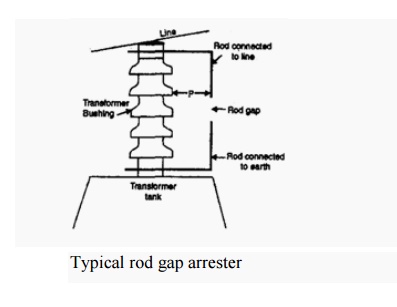
1.1. Rod gap arrester
It is a very simple type of diverter and consists
of two 1.5 cm rods, which are bent at right angles with a gap in between as
shown in Fig. One rod is connected to the line circuit and the other rod is
connected to earth. The distance between gap and insulator (i.e. distance P) must not be less than one third of
the gap length so that the arc may not reach the insulator and damage it.
Generally, the gap length is so adjusted that
breakdown should occur at 80% of spark-voltage in order to avoid cascading of
very steep wave fronts across the insulators.
The string of insulators for an overhead line on
the bushing of transformer has frequently a rod gap across it. Fig 8 shows the
rod gap across the bushing of a transformer. Under normal operating conditions,
the gap remains non-conducting. On the occurrence of a high voltage surge on
the line, the gap sparks over and the surge current is conducted to earth. In
this way excess charge on the line due to the surge is harmlessly conducted to
earth
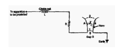
1.2 Horn gap arrester
Fig shows the horn
gap arrester. It consists of a horn shaped metal rods A and B separated by
a small air gap. The horns are so constructed that distance between them
gradually increases towards the top as shown. The horns are mounted on
porcelain insulators. One end of horn is connected to the line through a
resistance and choke coil L while the other end is effectively grounded.
The resistance R
helps in limiting the follow current to a small value. The choke coil is so
designed that it offers small reactance at normal power frequency but a very
high reactance at transient frequency. Thus the choke does not allow the
transients to enter the apparatus to be protected.
The gap between the horns is so adjusted that
normal supply voltage is not enough to cause an arc across the gap.
Under normal conditions, the gap is non-conducting
i.e. normal supply voltage is insufficient to initiate the arc between the gap.
On the occurrence of an over voltage, spark-over takes place across the small gap G. The heated air around the arc
and the magnetic effect of the arc cause the arc to travel up the gap. The arc
moves progressively into positions 1, 2 and 3.
At some position of the arc (position 3), the
distance may be too great for the voltage to maintain the arc; consequently,
the arc is extinguished. The excess charge on the line is thus conducted
through the arrester to the ground.
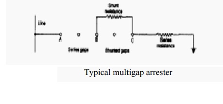
1.3 Multi gap arrester
Fig shows the multi
gap arrester. It consists of a series of metallic (generally alloy of zinc)
cylinders insulated from one another and separated by small intervals of air
gaps. The first cylinder (i.e. A) in the series is connected to the line and
the others to the ground through a series resistance. The series resistance
limits the power arc. By the inclusion of series resistance, the degree of
protection against traveling waves is reduced.
In order to overcome this difficulty, some of the
gaps (B to C in Fig) are shunted by resistance. Under normal conditions, the
point B is at earth potential and the normal supply voltage is unable to break
down the series gaps. On the occurrence an over voltage, the breakdown of
series gaps A to B occurs.
The heavy current after breakdown will choose the
straight ŌĆō through path to earth via the shunted gaps B and C, instead of the
alternative path through the shunt resistance.
1.4 Expulsion type arrester
This type of arrester is also called ŌĆśprotector tubeŌĆÖ and is commonly used on
system operating at voltages up to 33kV. Fig shows the essential parts of an expulsion type lightning arrester.
It essentially consists of a rod gap AAŌĆÖ in series
with a second gap enclosed within the fiber tube. The gap in the fiber tube is
formed by two electrodes. The upper electrode is connected to rod gap and the
lower electrode to the earth. One expulsion arrester is placed under each line
conductor.
Fig shows
the installation of expulsion arrester on an overhead line.
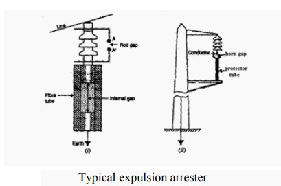
On the occurrence of an over voltage on the line,
the series gap AAŌĆÖ spanned and an arc is stuck between the electrodes in the
tube. The heat of the arc vaporizes some of the fiber of tube walls resulting
in the production of neutral gas. In an extremely short time, the gas builds up
high pressure and is expelled through the lower electrode, which is hollow. As
the gas leaves the tube violently it carries away ionized air around the arc..
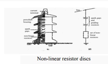
1.5 Valve type arrester
Valve
type arresters incorporate non linear resistors and are
extensively used on systems,
operating at high voltages. Fig shows the various parts of a valve type
arrester. It consists of two assemblies (i) series spark gaps and (ii)
non-linear resistor discs in series. The non-linear elements are connected in
series with the spark gaps. Both the assemblies are accommodated in tight
porcelain container.
The spark
gap is a
multiple assembly consisting of a number of identical spark gaps in series. Each gap consists of two electrodes with fixed gap
spacing. The voltage distribution across the gap is line raised by means of
additional resistance elements called grading resistors across the gap. The
spacing of the series gaps is such that it will withstand the normal circuit
voltage. However an over voltage will cause the gap to break down causing the
surge current to ground via the non-linear resistors.
The
non-linear resistor discs are made of inorganic compound such as thyrite or metrosil. These discs are connected
in series. The non-linear resistors have the property of offering a high
resistance to current flow when normal system voltage is applied, but a low
resistance to the flow of high surge currents. In other words, the resistance
of these non-linear elements decreases with the increase in current through
them and vice-versa.
Under
normal conditions, the normal system voltage is insufficient to cause the
breakdown of air gap assembly. On the occurrence of an over voltage, the
breakdown of the series spark gap takes place and the surge current is
conducted to earth via the non -linear resistors. Since the magnitude of surge
current is very large, the non-linear elements will offer a very low resistance
to the passage of surge. The result is that the surge will rapidly go to earth
instead of being sent back over the line. When the surge is over, the non
-linear resistors assume high resistance to stop the flow of current.
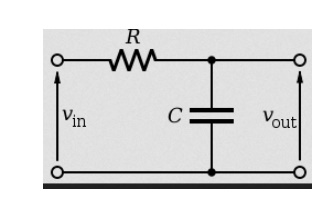
2. Low pass filter:
Low pass
filters are composed of series inductors and parallel capacitors in general
electric circuits. This LC combination provides a low impedance path to ground
for selected resonant frequencies. Low pass filters employ CLC to achieve
better protection even for high frequency transients. In surge protection
usage, voltage clamping devices are added in parallel to the capacitors.
A
low-pass filter is a filter that passes signals with a frequency lower than a
certain cutoff frequency and attenuates signals with frequencies higher than
the cutoff frequency. The amount of attenuation for each frequency depends on
the filter design. The filter is sometimes called a high-cut filter, or treble
cut filter in audio applications. A low-pass filter is the opposite of a
high-pass filter. A band-pass filter is a combination of a low-pass and a
high-pass filter.
Low-pass
filters exist in many different forms, including electronic circuits used in
audio, anti-aliasing filters for conditioning signals prior to
analog-to-digital conversion, digital filters for smoothing sets of data,
acoustic barriers, blurring of images, and so on. The moving average operation
used in fields such as finance is a particular kind of low-pass filter, and can
be analyzed with the same signal processing techniques as are used for other
low-pass filters.
3. Power Conditioners:
Low impedance power conditioners are used primarily to interface with the switch mode power supplies found in electronic equipment. Low impedance power conditioners differ from isolation transformer in that this conditioner have much lower impedance and have a filter. The filter is on the output side and protects against high frequency noise and impulses. Normally the neutral to ground connection can be made on load side because of the existence of an isolation transformer. However, low to medium frequency transients can cause problems for power conditioners.
Related Topics