Chapter: Embedded Systems Design : Design examples
Burglar alarm system
Digital echo unit
This design example follows the construction of a digital echo unit to
provide echo and reverb effects.
With sound samples digitally recorded, it is possible to use digital
signal processing techniques to create far better and more flexible effects
units (or sound processors, as they are more commonly called). Such units
comprise a fast digital signal processor with A to D and D to A converters and
large amounts of memory. An analogue signal is sent into the processor,
converted into the digital domain, processed using software running on the
processor to create filters, delay, reverb and other effects before being
converted back into an analogue signal and being sent out.
They can be completely software based, which provides a lot of
flexibility, or they can be pre-programmed. They can take in analogue or, in
some cases, digital data, and feed it back into other units or directly into an
amplifier or audio mixing desk, just like any other instrument.
Creating echo and reverb
Analogue echo and reverb units usually rely on an electromechanical
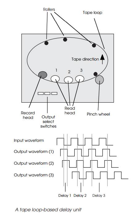
method of delaying an audio signal to create reverberation or echo. The WEM
Copycat used a tape loop and a set of tape heads to record the signal onto tape
and then read it from the three or more tape heads to provide three delayed
copies of the signal.
The delay was a function of the tape speed and the distance between the
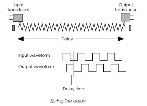
recording and read tape heads. This provides a delay of up to 1 second. Spring
line delays used a transducer to send the audio signal mechanically down a taut
spring where the delayed signal would be picked up again by another transducer.
Bucket brigade devices have also been used to create a purely electronic
delay. These devices take an analogue signal and pass it from one cell to
another using a clock. The technique is similar to passing a bucket of water by
hand down a line of men. Like the line of men, where some water is inevitably
lost, the analogue signal degrades — but it is good enough to achieve some good
effects.
With a digitised analogue signal, creating delayed cop-ies is easy. The
samples can be stored in memory in a buffer and later retrieved. The advantage
this offers is that the delayed
sample is an exact copy of the original sound and, unlike the techniques
previously described, has not degraded in quality or had tape noise introduced.
The number of delayed copies is dependent on the number of buffers and hence
the amount of memory that is available. This ability, coupled with a signal
processor allows far more accurate and natural echoes and reverb to be created.
The problem with many analogue echo and reverb units is that they
simplify the actual reverb and echo. In natural conditions, such as a large
concert hall, there are many delay sources as the sound bounces around and this
cannot be reproduced with only two or three voices which are independ-ently
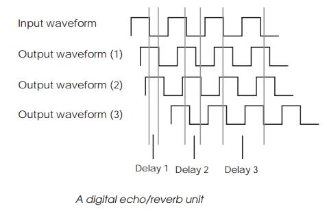
mixed together with a bit of feedback. The advantage of the digital approach is
that as many delays can be created as required and the signal processor can
combine and fade the different sources as needed to reproduce the environment
required.
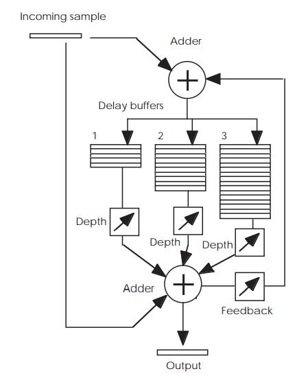
The block diagram shows how such a digital unit can be constructed. The
design uses three buffers to create three separate delays. These buffers are
initially set to zero and are FIFOs — first in, first out — thus the first
sample to be placed at the top of each buffer appears at the bottom at
different times and is delayed by the number of samples that each buffer holds.
The smaller the buffer, the smaller the delay. The outputs of the three buffers
are all individually reduced in size according to the depth required or the
prominence that the delayed sound has. A large value gives an echoing effect,
similar to that of a large room or hall. A small depth reduces it. The delayed
samples are combined by the adder with the original sample — hence the
necessity to clear the buffer initially to ensure that random values, which add
noise, do not get added before the first sample appears — to create the final
effect. A feedback loop takes some of the output signal, as determined by the
feedback control, and combines it with the original sample as it is stored in
the buffers. This effectively controls the decay of the delayed sounds and
creates a more natural effect.
This type of circuit can become more sophisticated by adapting the depth
with time and having separate independ-ent feedback loops and so on. This
circuit can also be the basis of other effects such as chorus, phasing and
flanging where the delayed signal is constantly delayed but varies. This can be
done by altering the timing of the sample storage into the buffers.
Design requirements
The design requirements for the echo unit are as follows:
•
It must provide storage for at
least one second on all its channels.
•
It must provide control over the
echo length and depth.
•
It must take analogue signals in
and provide analogue signals out.
•
The audio quality must be good
with a 20 kHz band-width.
Designing the codecs
The first decision concerns the A to D and D to A codec design. Many
lower specification units use 8 bit A to D and D to A units to digitise and
convert the delayed analogue signal. This signal does not need to be such good
quality as the original and using an 8 bit resolution converter saves on cost
and reduces the amount of memory needed to store the delayed signal. Such
systems normally add the delayed signal in the analogue domain and this helps
to cover any quality degrada-tion.
With this design, the quality requirement precludes the use of 8 bit
converters and effectively dictates that a higher quality codec is used. With
the advent of the Compact Disc, there are now plenty of high quality audio
codecs available with sample sizes of 12 or more bits. A top end device would
use 16 bit conversion and this would fit nicely with 16 bit memory. This is
also the sample size used with Compact Disc.
The next consideration is the conversion rate. To achieve a bandwidth of
20 kHz, a conversion rate of 40 kHz is needed. This has several knock-on
effects: it determines the number of samples needed to store one second of
digital audio and hence the amount of memory. It also defines the timing that
the system must adhere to remove any sampling errors. The proc-essor must be
able to receive the digitised audio, store it and copy it as necessary,
retrieve the output samples, combine them and convert them to the analogue
signals every 25 µs.
Designing the memory structures
In examining the codec design, some of the memory requirements have
already started to appear. The first require-ment is the memory storage for the
digital samples. For a single channel of delay where only a single delayed
audio signal is combined with the original signal, the memory storage is the
sample size multiplied by the sample rate and the total storage time taken. For
a 16 bit sample and a 40 kHz rate, 80000 bytes of storage needed. Rounding up,
this is equivalent to just over 78 kbytes of storage (a kbyte of memory is 1024
bytes and not 1000).
This memory needs to be organised as a by 16 structure which means that
the final design will need 40 k by 16 words of memory per second of audio. For
a system with three delayed audio sources, this is about 120 k words which
works out very nicely at two 128k by 8 RAM chips. The spare 8 kbytes in each
RAM chip can be used by the supervisor software that will run on the control
processor.
Now that the amount of memory is known, then the memory type and access
speed can be worked out. DRAM is applicable in this case but requires refresh
circuitry and be-cause it is very high density may not be cost effective. If 16
Mb DRAM is used then with a by 16 organisation, a single chip would provide 1
Mbyte of data storage which is far too much for this application. The other
potential problem is the effect of refresh cycles which would potentially
introduce sampling errors. This means that static RAM is probably the best
solu-tion.
To meet the 25 µs cycle time which includes a minimum of a data read and a data write,
this means that the overall access time must be significantly less than half of
the cycle time, i.e. less than 12.5 µs. This means that almost any
memory is capable of performing this function.
In addition, some form of non-volatile memory is needed to contain the
control software. This would normally be stored in an EPROM. However, the EPROM
access times are not good and therefore may not be suitable for running the
software directly. If the control program is small enough, then it could be
transferred from the EPROM to the FSRAM and executed from there.
The software design
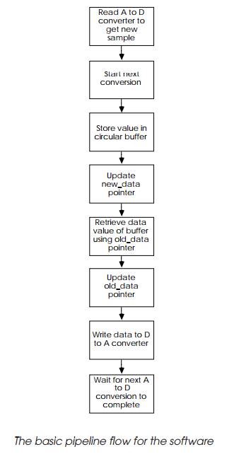
The software design is relatively simple and treats the process as a
pipeline. While the A to D is converting the next sample, the previous sample
is taken and stored in memory using a circular buffer to get the overall delay
effect. The next sample for D to A conversion and output is retrieved from the
buffer and sent to the converter. The circular buffer pointers are then
updated, including checking for the end of the buffer.
This sequence is repeated every 25 µs. While the proces-sor is not
performing this task, it can check and maintain the user controls. As stated
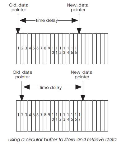
previously, circular buffers are used to hold the digitised data. A buffer is
used with two pointers: one points to the next storage location for the
incoming data and a second pointer is used to locate the delayed data. The next
two diagrams show how this works. Each sample is stored consecu-tively in
memory and the two pointers are separated by a constant value which is
equivalent to the number of samples delay that is required. In the example
shown, this is 16 samples. This difference is maintained so that when a new
sample is inserted, the corresponding old value is removed as well and then
both pointers are updated.
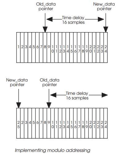
When either pointer reaches the end of the data block, its value is
changed to point to the next location. In the example shown, the New_data pointer is reset to point at the first location in the buffer which
held the first sample. This sample is no longer needed and its value can be
overwritten. By changing the difference between the two pointers, the time
delay can be changed. In practice, the pointers are simply memory addresses and
every time they are updated, they should be checked and if necessary reset to
the beginning of the table. This form of addressing is known as modulo
addressing and some DSP processors support it directly and therefore do not
need to check the address.
When using these structures, it is important to ensure that all values
are initially set to zero so that the delayed signal is not random noise when
the system first starts up. The delayed signal will not be valid until the
buffer has filled. In the examples shown, this would be 16 samples. Until this
point, the delayed signal will be made from the random contents of the buffer.
By clearing these values to zero, silence is effectively output and no noise is
heard until the correct delayed signal.
Multiple delays
With a multiple source system, the basic software design remains intact
except that the converted data is copied into several delay buffers and the
outputs from these buffers are combined before the end result is converted into
the analogue signal.
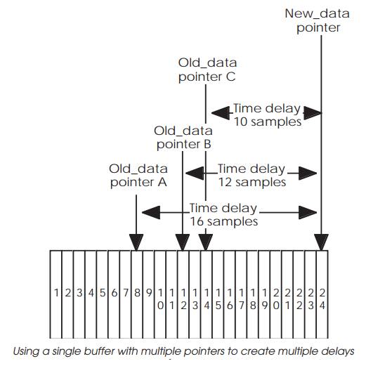
There are several ways of setting this up. The first is to use multiple
buffers and copy each new value into each buffer. Each buffer then supplies its
own delayed output which can be combined to create the final effect. A more
memory efficient system is to use a single buffer but add additional old_data
pointers with different time delays to create the
different delay length outputs.
The overhead in doing this is small. There is the mainte-nance of the
pointers to be done and the combination of the delay values to create the final
output for the D to A converter. This can be quite complex depending on the
level of sophisti-cation needed.
Digital or analogue adding
There are some options depending on the processing power available. With
a real echo or reverb, the delayed signals need to be gradually attenuated as
the signals die away and therefore, the delayed signal must be attenuated. This
can be done either digitally or in the analogue domain. With a single source,
the analogue implementation is easy. The delayed signal is converted and an
analogue mixer is used to attenuate and combine the delayed signal with the
original to create the reverb or echo effect. An analogue feedback bath can
also be created.
The multiple delayed source design can use this same analogue method but
requires a separate D to A converter for each delayed signal. This can be quite
expensive. Instead, the processor can add the signals together, along with
attenuation factors to create a combined delay signal that can be sent to the D
to A converter for combination with the original analogue signal. It is
therefore possible to perform all this, including the combination with the
original signal in the digital domain, and then simply output the end value to
the D to A converter. With this version, the attenuation does not need to be
constant and can be virtually any type of curve.
The disadvantage is the computation that is needed. The arithmetic that
is required is saturation arithmetic which is a little more than simply adding
two values together. This is needed to ensure that the combined value only
provides a peak value and not cause an overflow error. In addition, all the
calculations must be done within 25 µs to meet the sampling rate
criteria and this can be pushing the design a little with many general-purpose
processors.
Microprocessor selection
The choice of microprocessor is dependent on several factors. It must
have an address range of greater than 64 kbytes and have a 16 bit data path. It
must be capable of performing 16 bit arithmetic and thus this effectively rules
out 8 bit micro-processors and microcontrollers.
In terms of architecture, multiple address pointers that auto-increment
would make the circular buffer implementa-tions very efficient and therefore
some like a RISC processor or a fast MC68000 would be suitable. Other
architectures can certainly do the job but their additional overhead may reduce
their ability to perform all the processing within the 25 µs window
that there is. One way of finding this out is to create some test code and run
it on a simulator or emulator, for example, to find out how many clocks it does
take to execute these key routines.
A low cost DSP processor is also quite attractive in this type of
application, especially if it supports modulo address-ing and saturation
arithmetic.
The overall system design
The basic design for the system uses a hardware timer to generate a
periodic interrupt every 25 µs. The associated inter-rupt service routine is where the data from the
A to D converter is read and stored, the next conversion started and the
delayed data taken from the buffer and combined. The pointers are updated
before returning from the service routine. In this way, the sampling is done on
a regular basis and is given a higher priority than the background processing.
While the processor is not servicing the interrupt, it stays in a
forever loop, polling the user interface for parameters and commands. The delay
times are changed by manipulating the pointers. It is possible to do this by
changing the sampling rate instead but the audio quality does not stay
constant.
The system initialises by clearing the RAM to zero and using some of it
to hold the program code which is copied from EPROM. If a battery backed SRAM
is used instead, then used defined parameters and settings could be stored here
as well and retained when the system is switched off.
Related Topics