Chapter: Flexible Alternating Current Transmission System : Thyristor Controlled Series Capacitor (TCSC) and Applications
Applications of TCSC(Thyristor Controlled Series Capacitor)
APPLICATIONS
1. Introduction
Ø Thyristor-controlled
series capacitors (TCSCs) can be used for several power system performance
enhancements, namely, the improvement in system stability, the damping of power
oscillations, the alleviation of sub synchronous resonance (SSR), and the
prevention of voltage collapse.
Ø The
effectiveness of TCSC controllers is dependent largely on their proper
placement within the carefully selected control signals for achieving different
functions.
Ø Although
TCSCs operate in highly nonlinear power-system environments, linear-control
techniques are used extensively for the design of TCSC controllers.
2. Improvement of the System –
Stability Limit
Ø During
the outage of a critical line in a meshed system, a large volume of power tends
to flow in parallel transmission paths, which may become severely overloaded.
Ø Providing
fixed-series compensation on the parallel path to augment the power-transfer
capability appears to be a feasible solution, but it may increase the total
system losses.
Ø Therefore,
it is advantageous to install a TCSC in key transmission paths, which can adapt
its series-compensation level to the instantaneous system requirements and
provide a lower loss alternative to fixed-series compensation.
Ø The
series compensation provided by the TCSC can be adjusted rapidly to ensure
specified magnitudes of power flow along designated transmission lines.
Ø This
condition is evident from the TCSC’s efficiency, that is, ability to change its
power flow as a function of its capacitive-reactance setting:
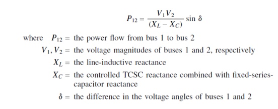
Ø This
change in transmitted power is further accomplished with minimal influence on
the voltage of interconnecting buses, as it introduces voltage in quadrature.
Ø In
contrast, the SVC improves power transfer by substantially modifying the
interconnecting bus voltage, which may change the power into any connected
passive loads.
Ø The
freedom to locate a TCSC almost anywhere in a line is a significant advantage.
Power-flow control does not necessitate the high-speed operation of power flow
control devices and hence discrete control through a TSSC may also be adequate
in certain situations.
Ø However,
the TCSC cannot reverse the power flow in a line, unlike HVDC controllers and
phase shifters.
3. Enhancement of System Damping
3.1 Introduction
Ø The TCSC
can be made to vary the series-compensation level dynamically in response to
controller-input signals so that the resulting changes in the power flow
enhance the system damping .The power modulation results in a corresponding
variation in the torques of the connected synchronous generators particularly
if the generators operate on constant torque and if passive bus loads are not
installed.
Ø The
damping control of a TCSC or any other FACTS controller should generally do the
following:
1. Stabilize
both post disturbance oscillations and spontaneously growing oscillations
during normal operation;
2. Obviate
the adverse interaction with high-frequency phenomena in power systems, such as
network resonances; and
3. Preclude
local instabilities within the controller bandwidth.
Ø In
addition, the damping control should
1. be robust
in that it imparts the desired damping over a wide range of system operating
conditions, and
2. be
reliable.
3.2 Principle of Damping
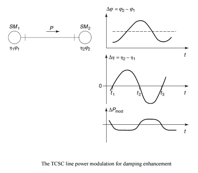
Ø The
concept of damping enhancement by line-power modulation can be illustrated with
the two-machine system depicted in Fig.
Ø The
machine SM1 supplies power
to the other machine, SM2,
over a lossless transmission line. Let the speed and rotor angle of machine SM1 be denoted by η1
and φ1, respectively; of machine SM2,
denoted by η2 and φ2, respectively.
Ø During a
power swing, the machines oscillate at a relative angle
∆φ = (φ2 − φ1).
Ø If the
line power is modulated by the TCSC to create an additional machine torque that
is opposite in sign to the derivative of the rotor-angle deviation, the
oscillations will get damped. This control strategy translates into the
following actions: When the receiving end–machine speed is lower than the
sending end–machine speed, that is, ∆h =(η2− η1 ) is
negative, the TCSC should increase power flow in the line.
Ø In other
words, while the sending-end machine accelerates, the TCSC control should
attempt to draw more power from the machine, thereby reducing the kinetic
energy responsible for its acceleration.
Ø On the
other hand, when ∆η is positive, the TCSC must decrease the power transmission
in the line.
Ø This
damping control strategy is depicted in Fig. through plots of the relative
machine angle ∆φ, the relative machine speed ∆η, and the incremental power
variation ∆Pmod.
Ø The
incremental variation of the line-power flow DP, given in megawatts (MW), with respect to DQTCSC, given in MVAR, is as follows

Ø Thus the
TCSC action is based on the variation of line-current magnitude and is
irrespective of its location.
Ø Typically,
the change in line-power transfer caused by the introduction of the full TCSC
is in the range of 1–2, corresponding to an angular difference (d) of 308–408
across the line.
Ø The
influence of any bus load on the torque/ power control of the synchronous
generator is derived for the case of a resistive load and completely inductive
generator impedance.
Ø The ratio
of change in generator power to the ratio of change in the power injected from
the line into the generator bus is expressed as
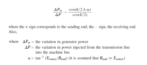
Ø The
effect of all practical passive loads is generally moderate, and the sign of
generator power is not changed. In the absence of any bus load,
∆Pm = ∆P.
Ø The
controlled-to-fixed ratio of capacitive reactance in most applications is in
the 0.05– 0.2 range, the exact value determined by the requirements of the
specific application.
3.3 Bang – Bang Control
Ø Bang-bang
control is a discrete control form in which the thyristors are either fully
switched on (α = 900) or fully switched off (α = 1800).
Ø Thus the
TCSC alternates between a fixed inductor and a fixed capacitor, respectively,
and it is advantageous that such control is used not only for minimizing first
swings but for damping any subsequent swings as well.
Ø Bang-bang
control is employed in face of large disturbances to improve the transient
stability.
3.4 Auxiliary Signals for TCSC Modulation
Ø The
supplementary signals that could be employed for modulating TCSC impedance are
listed in the text that follows:
3.4.1 Local Signals
Ø These
signals constitute the following:
1. The line
current,
2. The
real-power flow,
3. The bus
voltage, and
4. The local
bus frequency.
3.4.2
Remote
Signals
Ø These
signals constitute the following:
1. The
rotor-angle/ speed deviation of a remote generator,
2. The
rotor-angle/ speed (frequency) difference across the system, and
3. The
real-power flow on adjacent lines.
Ø The
angular difference between remote voltages can be synthesized by using local
voltages at the two terminals of the TCSC and through the line current.
Alternatively, a recent approach may be adopted wherein the phase angles of
remote areas can be measured directly by using synchronized phasor measurement
units.
Ø Adjacent-line
real-power flow can be measured remotely and transmitted to the TCSC control
system through telecommunication.
Ø Despite
telecommunication delays, this signal can be used satisfactorily and
economically for line power scheduling, which itself is a slow control.
Selection of Input Signals
Ø It is a
desirable feature that the TCSC controller input signals can extend as far as
possible without sensitivity to the TCSC output. This feature ensures that the
control signals represent mainly the system conditions for which the TCSC is
expected to improve.
Ø Local bus
frequency is seen to be less responsive to system power swings as compared to
the synthesized-voltage frequency,although both line current and bus voltage
are also shown to be fairly effective.
4. Voltage – Collapse Prevention
Ø Voltage-collapse
problems are a serious concern for power-system engineers and planners.
Ø Voltage
collapse is mathematically indicated when the system Jacobian becomes singular.
Ø The
collapse points are indicative of the maximum load ability of the transmission
lines or the available transfer capability (ATC).
Ø The TCSCs
can significantly enhance the load ability of transmission networks, thus
obviating voltage collapse at existing power-transfer levels.
Ø The TCSC
reduces the effective line reactance, thereby increasing the power flow; it
generates reactive power with increasing through-current, thus exercising a
beneficial influence on the neighboring bus voltage.
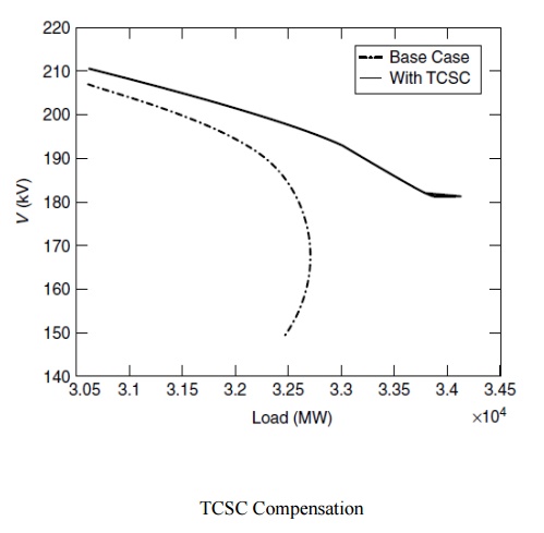
Ø The
system faces voltage collapse or a maximum loading point corresponding to a
2120-MW increase in the net load.
Ø If a TCSC
is installed to provide 50% compensation of the line experiencing the highest
increase in power at the point of collapse, the maximum load ability will be
enhanced to 3534 MW.
Ø The
influence of the TCSC on the voltage profile of a critical bus is illustrated
in Fig.
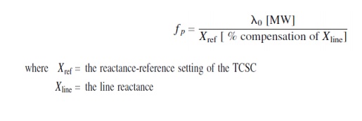
Ø A performance
factor, fp, is proposed in
that indicates the maximum increase in load ability, λ0, for a given
percent of line compensation:
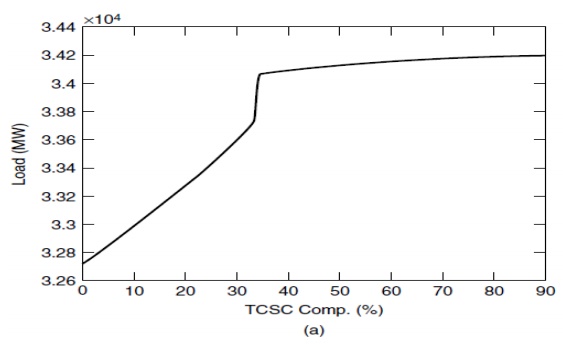
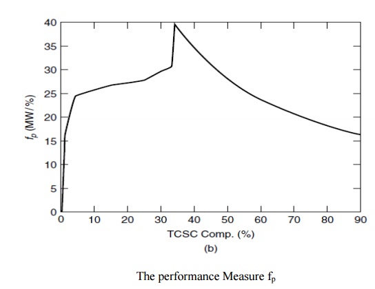
Ø This
index can be gainfully employed to obtain the best location of the TCSC in a
system.
Ø The
enhancement of system loading and variation of the performance factor with TCSC
compensation are depicted in Fig.
Ø It is
suggested that TCSC reactance-modulation schemes based on line current or line
power, or on the angular difference across lines, may prove unsuccessful for
voltage-stability enhancement. The reason is that these controls constrain any
variation in the corresponding variables that may be necessary with changing
loads, thereby limiting any power-flow enhancement on the line.
Related Topics