Chapter:
Common types of Comparators
COMPARATORS
Comparators are one form of linear
measurement device which is quick and more convenient for checking large number
of identical dimensions. Comparators normally will not show the actual
dimensions of the work piece. They will be shown only the deviation in size.
i.e. During the measurement a comparator is able to give the deviation of the
dimension from the set dimension. This cannot be used as an absolute measuring
device but can only compare two dimensions. Comparators are designed in several
types to meet various conditions. Comparators of every type incorporate some
kind of magnifying device. The magnifying device magnifies how much dimension
deviates, plus or minus, from the standard size.
The comparators are classified according
to the principles used for obtaining magnification. The common types are:
1) Mechanical
comparators
2) Electrical
comparators
3) Optical
comparators
4) Pneumatic
comparators
1) MECHANICAL
COMPARATORS
Mechanical comparator employs mechanical
means for magnifying small deviations. The method of magnifying small movement
of the indicator in all mechanical comparators are effected by means of levers,
gear trains or a combination of these elements. Mechanical comparators are
available having magnifications from 300 to 5000 to 1. These are mostly used
for inspection of small parts machined to close limits.
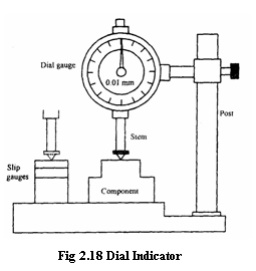
1. Dial indicator
A dial indicator or dial gauge is used
as a mechanical comparator. The essential parts of the instrument are like a
small clock with a plunger projecting at the bottom as shown in fig. Very
slight upward movement on the plunger moves it upward and the movement is
indicated by the dial pointer. The dial is graduated into 100 divisions. A full
revolution of the pointer about this scale corresponds to 1mm travel of the
plunger. Thus, a turn of the pointer b one scale division represents a plunger
travel of 0.01mm.
Experimental
setup
The whole setup consists of worktable, dial
indicator and vertical post. The dial indicator is fitted to vertical post by
on adjusting screw as shown in fig. The vertical post is fitted on the work
table; the top surface of the worktable is finely finished. The dial gauge can
be adjusted vertically and locked in position by a screw.
Procedure
Let us assume that the required height of the
component is 32.5mm. Initially this height is built up with slip gauges. The
slip gauge blocks are placed under the stem of the dial gauge. The pointer in
the dial gauge is adjusted to zero. The slip gauges are removed.
Now the component to be
checked is introduced under the stem of the dial gauge. If there is any
deviation in the height of the component, it will be indicated by the pointer.
Mechanism
The stem has rack
teeth. A set of gears engage with the rack. The pointer is connected to a small
pinion. The small pinion is independently hinged. I.e. it is not connected to
the stern. The vertical movement of the stem is transmitted to the pointer
through a set of gears. A spring gives a constant downward pressure to the
stem.
2.
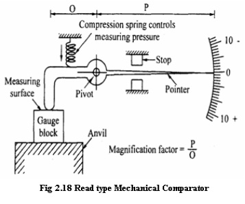
Read type mechanical comparator
In this type of
comparator, the linear movement of the plunger is specified by means of read
mechanism. The mechanism of this type is illustrated in fig. A spring-loaded
pointer is pivoted. Initially, the comparator is set with the help of a known
dimension eg. Set of slip gauges as shown in fig. Then the indicator reading is
adjusted to zero. When the part to be measured is kept under the pointer, then
the comparator displays the deviation of this dimension either in ± or— side of
the set dimension.
Advantages
1) It
is usually robust, compact and easy to handle.
2) There
is no external supply such as electricity, air required.
3) It
has very simple mechanism and is cheaper when compared to other types.
4) It
is suitable for ordinary workshop and also easily portable.
Disadvantages
1)
Accuracy of the comparator mainly
depends on the accuracy of the rack and pinion arrangement. Any slackness will
reduce accuracy.
2) It
has more moving parts and hence friction is more and accuracy is less.
3)
The range of the instrument is limited
since pointer is moving over a fixed scale.
2) ELECTRICAL
COMPARATOR:
An
electrical comparator consists of the following three major part such as
1) Transducer
2) Display
device as meter
3) Amplifier
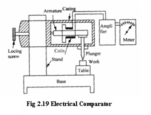
Transducer
An iron armature is provided in between
two coils held by a lea spring at one end. The other end is supported against a
plunger. The two coils act as two arms of an A.C. wheat stone bridge circuit.
Amplifier
The amplifier is nothing but a device
which amplifies the give input signal frequency into magnified output
Display
device or meter
The amplified input signal is displayed
on some terminal stage instruments. Here, the terminal instrument is a meter.
Working
principle
If the armature is centrally located
between the coils, the inductance of both coils will be equal but in opposite
direction with the sign change. Due to this, the bridge circuit of A.C. wheat
stone bridge is balanced. Therefore, the meter will read zero value. But
practically, it is not possible. In real cases, the armature may be lifted up
or lowered down by the plunger during the measurement. This would upset the
balance of the wheat stone bridge circuit. Due to this effect, the change in
current or potential will be induced correspondingly. On that time, the meter
will indicate some value as displacement. This indicated value may be either
for larger or smaller components. As this induced current is too small, it
should be suitably amplified before being displayed in the meter.
Checking
of accuracy
To check the accuracy of a given specimen or work,
first a standard specimen is placed under the plunger. After this, the
resistance of wheat stone bridge is adjusted so that the scale reading shows
zero. Then the specimen is removed. Now, the work is introduced under the
plunger. If height variation of work presents, it will move the plunger up or
down. The corresponding movement of the plunger is first amplified by the
amplifier then it is transmitted to the meter to show the variations. The least
count of this electrical comparator is 0.001mm (one micron).
3)ELECTRONIC COMPARATOR
In electronic
comparator, transducer induction or the principle of application of frequency
modulation or radio oscillation is followed.
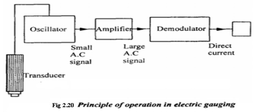
Construction
details
In
the electronic comparator, the following components are set as follows:
i. Transducer
ii. Oscillator
iii. Amplifier
iv.Demodulator
v. Meter
(i)
Transducer
It converts the
movement of the plunger into an electrical signal. It is connected with
oscillator.
(ii)
Oscillator
The oscillator which receives electrical
signal from the transducer and raises the amplitude of frequency wave by adding
carrier frequency called as modulation.
(iii)
Amplifier
An amplifier is connected in between
oscillator and demodulator. The signal coming out of the oscillator is
amplified into a required level.
(iv)
Demodulator
Demodulator is nothing but a device
which cuts off external carrier wave frequency. i.e. It converts the modulated
wave into original wave as electrical signal.
(v)
Meter
This is nothing but a display device
from which the output can be obtained as a linear measurement.
Principle
of operation
The work to be measured is placed under
the plunger of the electronic comparator. Both work and comparator are made to
rest on the surface plate. The linear movement of the plunger is converted into
electrical signal by a suitable transducer. Then it sent to an oscillator to
modulate the electrical signal by adding carrier frequency of wave. After that
the amplified signal is sent to demodulator in which the carrier waves are cut
off. Finally, the demodulated signal is passed to the meter to convert the
probe tip movement into linear measurement as an output signal. A separate
electrical supply of D.C. is already given to actuate the meter.
Advantages of
Electrical and Electronic comparator
1) It
has less number of moving parts.
2) Magnification
obtained is very high
3)
Two or more magnifications are provided
in the same instrument to use various ranges.
4) The
pointer is made very light so that it is more sensitive to vibration.
5) The
instrument is very compact.
Disadvantages of
Electrical and Electronic comparator
1) External
agency is required to meter for actuation.
2) Variation
of voltage or frequency may affect the accuracy of output.
3) Due
to heating coils, the accuracy decreases.
4) It
is more expensive than mechanical comparator.