Chapter: Civil Surveying : Total Station
Sources of Error for Total Stations
SOURCES OF ERROR FOR TOTAL STATIONS
1 CALIBRATION OF TOTAL STATIONS
To maintain the high level of
accuracy offered by modern total stations, there is now much more emphasis on
monitoring instrumental errors, and with this in mind, some construction sites
require all instruments to be checked on a regular basis using procedures
outlined in the quality manuals.
Some instrumental errors are
eliminated by observing on two faces of the total station and averaging, but
because one face measurements are the preferred method on site, it is important
to determine the magnitude of instrumental errors and correct for them.
For total stations, instrumental
errors are measured and corrected using electronic calibration procedures that
are carried out at any time and can be applied to the instrument on site. These
are preferred to the mechanical adjustments that used to be done in labs by
technician.
Since calibration parameters can
change because of mechanical shock, temperature changes and rough handling of
what is a high-precision instrument, an electronic calibration should be
carried our on a total station as follows:
Before using the instrument for the first time
After long storage periods
After rough or long transportation
After long periods of work
Following big changes in temperature
Regularly for precision surveys
Before each calibration, it is
essential to allow the total station enough to reach the ambient temperature.
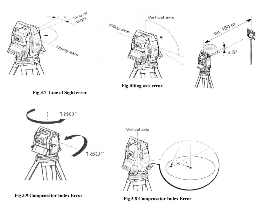
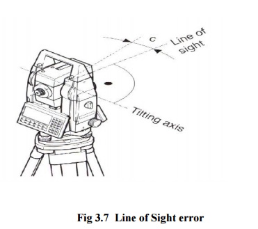
2 HORIZONTAL COLLIMATION (OR LINE OF SIGHT ERROR)
This axial error is caused when
the line of sight is not perpendicular to the tilting axis. It affects all
horizontal circle readings and increases with steep sightings, but this is
eliminated by observing on two faces. For single face measurements,
an on-board calibration function is used to
determine c, the deviation between the actual line of sight and a line
perpendicular to the tilting axis. A correction is then applied automatically
for this to all horizontal circle readings.
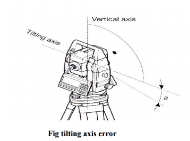
3 TILTING
AXIS ERROR
This axial errors occur when the
titling axis of the total station is not perpendicular to its vertical axis.
This has no effect on sightings taken when the telescope is horizontal, but
introduces errors into horizontal circle readings when the
telescope is tilted, especially for steep
sightings. As with horizontal collimation error, this error is eliminated by
two face measurements, or the tilting axis error a is measured in a calibration
procedure and a correction applied for this to all horizontal circle readings - as
before if a is too big, the instrument should be returned to the manufacture.
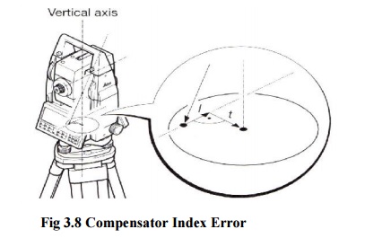
4 COMPENSATOR INDEX ERROR
Errors caused by not levellinga
theodolite or total station carefully cannot be eliminated by taking face left
and face right readings. If the total station is fitted with a compensator it
will measure residual tilts of the instrument and will apply corrections to the
horizontal and vertical angles for these.
However all compensators will have a longitudinal
error l and traverse error t known as zero point errors. These
are averaged using face left and face right readings but for single face
readings must be determined by the calibration function of the total station.
A vertical collimation error
exists on a total station if the 0o to 180o line in the
vertical circle does not coincide with its vertical axis. This zero point error
is present in all vertical circle readings and like the horizontal collimation
error, it is eliminated by taking FL and FR readings or by determining i
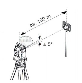
For all of the above total station errors
(horizontal and vertical collimation, tilting axis and compensator) the total
station is calibrated using an in built function. Here the function is
activated and a measurement to a target is taken as shown below.
Following the first measurement
the total station and the telescope are each rotated through 180o and the
reading is repeated.
Any difference between the measured horizontal and
vertical angles is then quantified as an instrumental error and applied to all
subsequent readings automatically. The total station is thus calibrated and the
procedure is the same for all of the above error type.
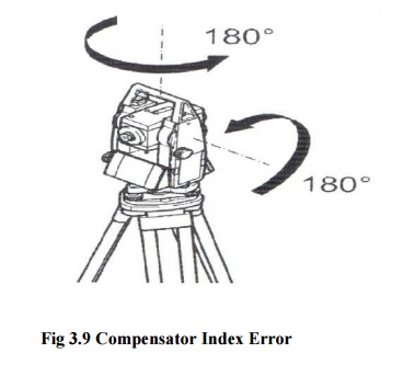
Fig 3.9 Compensator Index Error