Chapter: Flexible Alternating Current Transmission System : Co-Ordination of FACTS Controllers
Co-Ordination of Multiple Controllers using Linear - Control Techniques
Co-Ordination of Multiple
Controllers using Linear – Control Techniques
1. Introduction
Ø The term coordination does not imply centralized
control; rather, it implies the simultaneous tuning of the controllers to
attain an effective, positive improvement of the overall control scheme.
Ø It is
understood that each controller relies primarily on measurements of locally
available quantities and acts independently on the local FACTS equipment.
2. The Basic Procedure for
Controller Design
The
controller-design procedure involves the following steps:
1. Derivation
of the system model;
2. Enumeration
of the system-performance specifications;
3. Selection
of the measurement and control signals;
4. Coordination of the controller design; and
5. Validation
of the design and performance evaluation.
Step 1: Derivation of System Model
Ø First, a
reduced-order nonlinearsystem model must be derived for the original power
system and this model should retain the essential steady-state and dynamic
characteristics of the power system .
Ø Then, the
model is linearized around an operating point to make it amenable to the
application of linear-control design techniques. If a controllermust be
designed for damping electromechanical oscillations, a further reducedlinear
model is selected that exhibits the same modal characteristics over the
relevant narrow range of frequencies as the original system.
Ø In
situations where linearized-system models may not be easily obtainable,
identification techniques are employed to derive simple linear models from
time-response information.
Step 2: Enumeration of the System – performance
Specifications
Ø The damping controller is expected to satisfy
the following criteria.
1. It should
help the system survive the first few oscillations after a severe system
disturbance with an adequate safety margin. This safety factor is usually
specified in terms of bus-voltage levels that should not be violated after a
disturbance.
2. A minimum
level of damping must be ensured in the steady state after a disturbance.
3. Potentially
deleterious interactions with other installed controls should be avoided or
minimized.
4. Desired
objectives over a wide range of system-operating conditions should be met
(i.e., it should be robust).
Step 3: Selection of the Measurement and Control
Signals
Ø The
choice of appropriate measurement and control signals is crucial to controller
design.
Ø The
signals must have high observability and controllability of the relevant modes
to be damped, and furthermore, the signals should only minimally affect the
other system modes.
Ø The
selection of these signals is usually based on system-modal magnitudes, shapes,
and sensitivties—all of which can be obtained from small-signal-stability
analysis.
Step 4: Controller Design and Coordination
Ø The FACTS
controller structures are usually chosen from industry practice. Typically, the
controller transfer function, Hj(s), of controller j is assumed to be
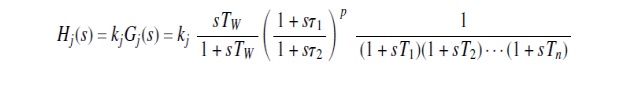
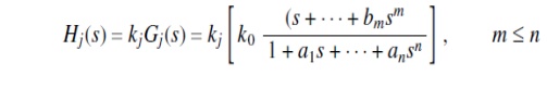
Ø This
transfer function consists of a gain, a washout stage, and a pth-order leadlag block, as well as
low-pass filters. Alternatively, it can be expressed as
Ø Although
the basic structure of different controllers is assumed as from the preceding
text, the coordination of controllers involves the simultaneous selection of
gains and time constants through different techniques.
Ø Doing so
permits the system-operating constraints and damping criteria to be satisfied
over a wide range of operating conditions.
Ø The
coordination techniques may use linearized models of the power system and other
embedded equipments, capitalizing on the existing sparsity in system
representation.
Ø This
model may be further reduced by eliminating certain algebraic variables yet
still retaining the essential system behavior in the frequency range of
interest.
Ø Eigenvalue
analysis–based controller-optimization and -coordination techniques are
applicable to power systems typically with a thousand states occurring when
full modal analysis must be performed. However, sometimes a limited number of
electromechanical modes must be damped; hence the eigenvalue analysis of a
selected region can be performed even for relatively larger power systems.
Step 5: Validation of the Design and performance
Evaluation
Ø Even
though the controller design is performed on the simplified system model, the
performance of the controller must still be established by using the most
detailed system model.
Ø The controller
should meet the specifications over a wide range of operating conditions and
consider all credible contingencies.This validation is generally performed with
nonlinear time-domain
Ø simulations
of the system.
Related Topics