Chapter: Civil Surveying : Total Station
Classification of Total Stations
CLASSIFICATION OF
TOTAL STATIONS
1 ELECTRO-
OPTICAL SYSTEM
1.1DISTANCE MEASUREMENT
When a distance is measured with a total station, am
electromagnetic wave or pulse is used for the measurement - this is
propagated through the atmosphere from the instrument to reflector or target
and back during the measurement.
Distances are measured using two methods: the
phase shift method, and the pulsed laser method.
This technique uses continuous electromagnetic
waves for distance measurement although these are complex in nature,
electromagnetic waves can be represented in their simplest from as periodic
waves.
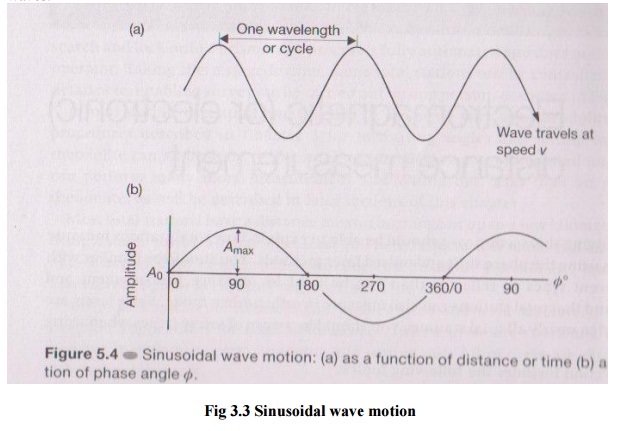
Fig 3.3
Sinusoidal wave motion
The wave completes a cycle when moving between identical
points on the wave and the number of times in one second the wave completes the
cycle is called the frequency of the wave. The speed of the wave is then used
to estimate the distance.
2 LASER
DISTANCE MEASUREMENT
In many total stations, distances
are obtained by measuring the time taken for a pulse of laser radiation to
travel from the instrument to a prism (or target) and back. As in the phase
shift method, the pulses are derived an infrared or visible laser diode and
they are transmitted through the telescope towards the remote end of the
distance being measured, where they are reflected and returned to the
instrument.
Since the velocity v of
the pulses can be accurately determined, the distance D can be obtained
using 2D = vt, where t is the time taken for a single pulse to
travel from instrument - target -
instrument.
This is also known as the timed-pulse or time-of-flight measurement
technique.
The transit time t is
measured using electronic signal processing techniques. Although only a single
pulse is necessary to obtain a distance, the accuracy obtained would be poor.
To improve this, a large number of pulses (typically
20,000 every second) are analysed during each measurement to
give a more accurate distance.
The pulse laser method is a much
simpler approach to distance measurement than the phase shift method, which was
originally developed about 50 years ago.
SLOPE AND HORIZONTAL DISTANCES
Both the phase shift and pulsed
laser methods will measure a slope distance L from the total station
along the line of sight to a reflector or target. For most surveys the
horizontal distance D is required as well as the vertical component V
of the slope distance.
Horizontal distance D = L cos?
=
L sin z
Vertical distance = V = L sin?
=
L cos z
Where ? is the vertical angle and z is
the is the zenith angle. As far
as the user
is
concerned, these calculations are seldom done because the
total station will
either display D and V automatically
or will dislplay L first and then D and V after pressing
buttons
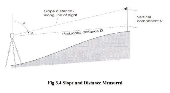
Fig 3.4
Slope and Distance Measured
How accuracy of distance measurement is specified
All total stations have a linear accuracy quoted in the form
�(a mm +
b ppm)
The constant a is independent of
the length being measured and is made up of internal sources within the
instrument that are normally beyond the control of the user. It is an estimate
of the individual errors caused by such phenomena as unwanted phase shifts in
electronic components, errors in phase and transit time measurements.
The systematic error b is proportional to the distance being
measured, where 1 ppm (part per million) is equivalent to an additional error
of 1mm for every kilometre measured.
Typical
specifications for a total station vary from �(2mm + 2ppm) to �(5mm + 5 pmm).
For
example: �(2mm + 2ppm), at 100m the error in distance measurement will be
�2mm but
at 1.5km, the error will be �(2mm + [2mm/km * 1.5km]) = �5m m
Reflectors used in distance measurement
Since the waves or pulses
transmitted by a total station are either visible or infrared, a plane mirror
could be used to reflect them. This would require a very accurate alignment of
the mirror, because the transmitted wave or pulses have a narrow spread.
To get around this problem special mirror prisms
are used as shown below.
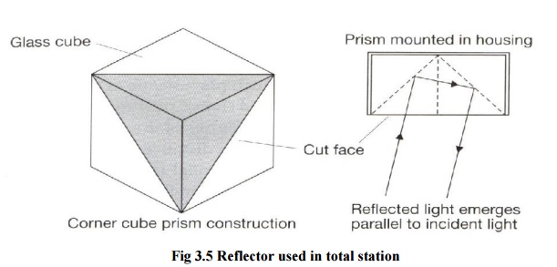
Fig 3.5
Reflector used in total station