Chapter: Transmission Lines and Waveguides : Passive Filters
Characteristics impedance of symmetrical networks, Constant K, Low pass, High pass, Band pass
Characteristics impedance of symmetrical networks, Constant K, Low pass, High pass, Band pass
Constant k filter
Constant k filters, also k-type filters, are a type of electronic filter designed using the image method. They are the original and simplest filters produced by this methodology and consist of a ladder network of identical sections of passive components. Historically, they are the first filters that could approach the ideal filter frequency response to within any prescribed limit with the addition of a sufficient number of sections. However, they are rarely considered for a modern design, the principles behind them having been superseded by other methodologies which are more accurate in their prediction of filter response.
Terminology
Some of the impedance terms and section terms used in this article are pictured in the diagram below. Image theory defines quantities in terms of an infinite cascade of two-port sections, and in the case of the filters being discussed, an infinite ladder network of L-sections. Here "L" should not be confused with the inductance L – in electronic filter topology, "L" refers to the specific filter shape which resembles inverted letter "L".
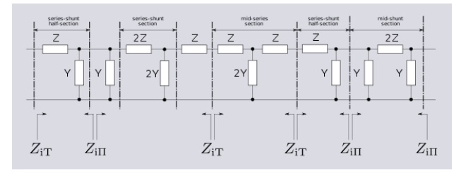
The sections of the hypothetical infinite filter are made of series elements having impedance 2Z and shunt elements with admittance 2Y. The factor of two is introduced for mathematical convenience, since it is usual to work in terms of half-sections where it disappears. The image impedance of the input and output port of a section will generally not be the same. However, for a mid-series section (that is, a section from halfway through a series element to halfway through the next series element) will have the same image impedance on both ports due to symmetry. This image impedance is designated ZiT due to the "T" topology of a mid-series section. Likewise, the image impedance of a mid-shunt section is designated ZiΠ due to the "Π" topology. Half of such a "T" or "Π" section is called a half-section, which is also an L-section but with half the element values of the full L-section. The image impedance of the half-section is dissimilar on the input and output ports: on the side presenting the series element it is equal to the mid-series ZiT, but on the side presenting the shunt element it is equal to the mid-shunt ZiΠ . There are thus two variant ways of using a half-section.
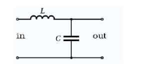
Constant k low-pass filter half section. Here inductance L is equal Ck2
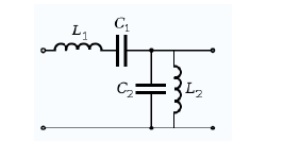
Constant k band-pass filter half section. L1 = C2k2 and L2 = C1k2
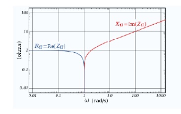
Image impedance ZiT of a constant k prototype low-pass filter is plotted vs. frequency ω. The impedance is purely resistive (real) below ωc, and purely reactive (imaginary) above ωc.
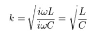
The building block of constant k filters is the half-section "L" network, composed of a series impedance Z, and a shunt admittance Y. The "k" in "constant k" is the value given by
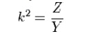
Thus, k will have units of impedance, that is, ohms. It is readily apparent that in order for k to be constant, Y must be the dual impedance of Z. A physical interpretation of k can be given by observing that k is the limiting value of Zi as the size of the section (in terms of values of its components, such as inductances, capacitances, etc.) approaches zero, while keeping k at its initial value. Thus, k is the characteristic impedance, Z0, of the transmission line that would be formed by these infinitesimally small sections. It is also the image impedance of the section at resonance, in the case of band-pass filters, or at ω = 0 in the case of low-pass filters.[7] For example, the pictured low-pass half-section has
Elements L and C can be made arbitrarily small while retaining the same value of k. Z and Y however, are both approaching zero, and from the formulae (below) for image impedances
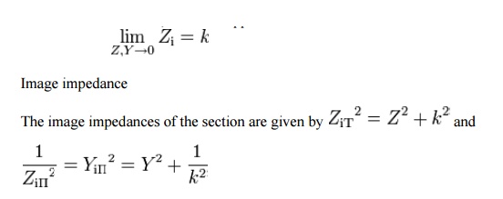
Provided that the filter does not contain any resistive elements, the image impedance in the pass band of the filter is purely real and in the stop band it is purely imaginary. For example, for the pictured low-pass half-section.
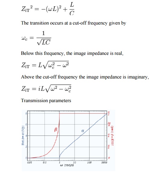
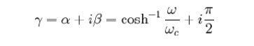
The transfer function of a constant k prototype low-pass filter for a single half-section showing attenuation in nepers and phase change in radians.
See also: Image impedance#Transfer function
The transmission parameters for a general constant k half-section are given by
For the low-pass L-shape section, below the cut-off frequency, the transmission parameters are given by

That is, the transmission is lossless in the pass-band with only the phase of the signal changing. Above the cut-off frequency, the transmission parameters are:
Prototype transformations
The presented plots of image impedance, attenuation and phase change correspond to a low-pass prototype filter section. The prototype has a cut-off frequency of ωc = 1 rad/s and a nominal impedance k = 1 Ω. This is produced by a filter half-section with inductance L = 1 henry and capacitance C = 1 farad. This prototype can be impedance scaled and frequency scaled to the desired values. The low-pass prototype can also be transformed into high-pass, band-pass or band-stop types by application of suitable frequency transformations.
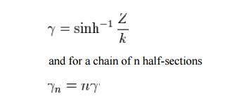
Cascading sections
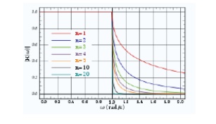
Gain response, H(ω) for a chain of n low-pass constant-k filter half-sections.
Several L-shape half-sections may be cascaded to form a composite filter. Like impedance must always face like in these combinations. There are therefore two circuits that can be formed with two identical L-shaped half-sections. Where a port of image impedance ZiT faces another ZiT, the section is called a Π section. Where ZiΠ faces ZiΠ the section so formed is a T section. Further additions of half-sections to either of these section forms a ladder network which may start and end with series or shunt elements.
It should be borne in mind that the characteristics of the filter predicted by the image method are only accurate if the section is terminated with its image impedance. This is usually not true of the sections at either end, which are usually terminated with a fixed resistance. The further the section is from the end of the filter, the more accurate the prediction will become, since the effects of the terminating impedances are masked by the intervening sections.
Filter fundamentals – Pass and Stop bands.
Filters of all types are required in a variety of applications from audio to RF and across the whole spectrum of frequencies. As such RF filters form an important element within a variety of scenarios, enabling the required frequencies to be passed through the circuit, while rejecting those that are not needed.
The ideal filter, whether it is a low pass, high pass, or band pass filter will exhibit no loss within the pass band, i.e. the frequencies below the cut off frequency. Then above this frequency in what is termed the stop band the filter will reject all signals.
In reality it is not possible to achieve the perfect pass filter and there is always some loss within the pass band, and it is not possible to achieve infinite rejection in the stop band. Also there is a transition between the pass band and the stop band where the response curve falls away, with the level of rejection rises as the frequency moves from the pass band to the stop band.
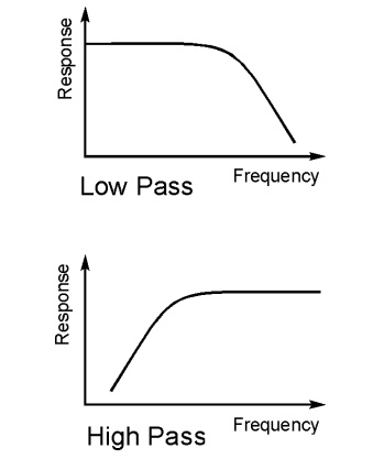
Basic types of RF filter
There are four types of filter that can be defined. Each different type rejects or accepts signals in a different way, and by using the correct type of RF filter it is possible to accept the required signals and reject those that are not wanted. The four basic types of RF filter are:
• Low pass filter
• High pass filter
• Band pass filter
• Band reject filter
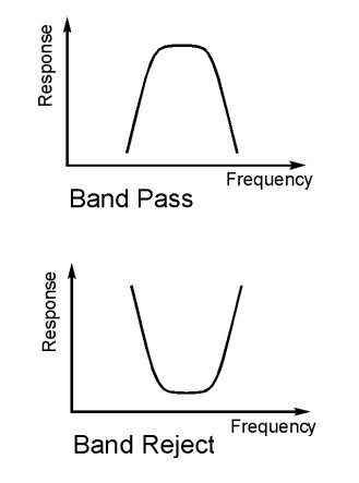
As the names of these types of RF filter indicate, a low pass filter only allows frequencies below what is termed the cut off frequency through. This can also be thought of as a high reject filter as it rejects high frequencies. Similarly a high pass filter only allows signals through above the cut off frequency and rejects those below the cut off frequency. A band pass filter allows frequencies through within a given pass band. Finally the band reject filter rejects signals within a certain band. It can be particularly useful for rejecting a particular unwanted signal or set of signals falling within a given bandwidth.
Filter frequencies
A filter allows signals through in what is termed the pass band. This is the band of frequencies below the cut off frequency for the filter. The cut off frequency of the filter is defined as the point at which the output level from the filter falls to 50% (-3 dB) of the in band level, assuming a constant input level. The cut off frequency is sometimes referred to as the half power or -3 dB frequency. The stop band of the filter is essentially the band of frequencies that is rejected by the filter. It is taken as starting at the point where the filter reaches its required level of rejection.
Filter classifications
Filters can be designed to meet a variety of requirements. Although using the same basic circuit configurations, the circuit values differ when the circuit is designed to meet different criteria. In band ripple, fastest transition to the ultimate roll off, highest out of band rejection are some of the criteria that result in different circuit values. These different filters are given names, each one being optimised for a different element of performance. Three common types of filter are given below:
• Butterworth: This type of filter provides the maximum in band flatness.
• Bessel: This filter provides the optimum in-band phase response and therefore also provides the best step response.
• Chebychev: This filter provides fast roll off after the cut off frequency is reached. However this is at the expense of in band ripple. The more in band ripple that can be tolerated, the faster the roll off.
• Elliptical: This has significant levels of in band and out of band ripple, and as expected the higher the degree of ripple that can be tolerated, the steeper it reaches its ultimate roll off.
RF filters are widely used in RF design and in all manner of RF and analogue circuits in general. As they allow though only particular frequencies or bands of frequencies, they are an essential tool for the RF design engineer.
Related Topics