Chapter: Transmission Lines and Waveguides : Passive Filters
Band Elimination, m-derived sections m-derived filter
Band Elimination, m-derived sections m-derived filter:
m-derived filters or m-type filters are a type of electronic filter designed using the image method. They were invented by Otto Zobel in the early 1920s. This filter type was originally intended for use with telephone multiplexing and was an improvement on the existing constant k type filter. The main problem being addressed was the need to achieve a better match of the filter into the terminating impedances. In general, all filters designed by the image method fail to give an exact match, but the m-type filter is a big improvement with suitable choice of the parameter m. The m-type filter section has a further advantage in that there is a rapid transition from the cut-off frequency of the pass band to a pole of attenuation just inside the stop band. Despite these advantages, there is a drawback with m-type filters; at frequencies past the pole of attenuation, the response starts to rise again, and m-types have poor stop band rejection. For this reason, filters designed using m-type sections are often designed as composite filters with a mixture of k-type and m-type sections and different values of m at different points to get the optimum performance from both types.
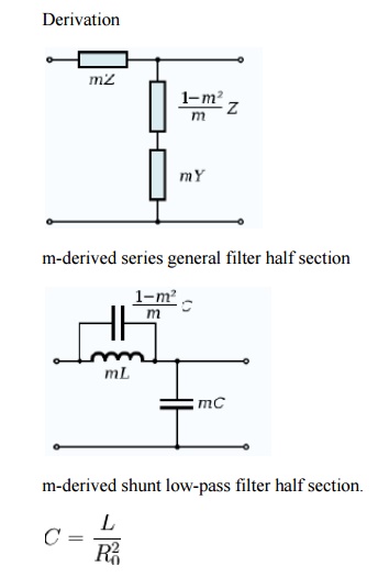
The building block of m-derived filters, as with all image impedance filters, is the "L" network, called a half-section and composed of a series impedance Z, and a shunt admittance Y. The m-derived filter is a derivative of the constant k filter. The starting point of the design is the values of Z and Y derived from the constant k prototype and are given by
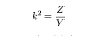
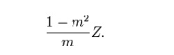
where k is the nominal impedance of the filter, or R0. The designer now multiplies Z and Y by an arbitrary constant m (0 < m < 1). There are two different kinds of m-derived section; series and shunt. To obtain the m-derived series half section, the designer determines the impedance that must be added to 1/mY to make the image impedance ZiT the same as the image impedance of the original constant k section. From the general formula for image impedance, the additional impedance required can be shown to be
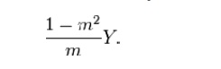
To obtain the m-derived shunt half section, an admittance is added to 1/mZ to make the image impedance ZiΠ the same as the image impedance of the original half section. The additional admittance required can be shown to be
The general arrangements of these circuits are shown in the diagrams to the right along with a specific example of a low pass section.
A consequence of this design is that the m-derived half section will match a k-type section on one side only. Also, an m-type section of one value of m will not match another m-type section of another value of m except on the sides which offer the Zi of the k-type.
Operating frequency
For the low-pass half section shown, the cut-off frequency of the m-type is the same as the k-type and is given by
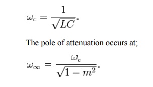
From this it is clear that smaller values of m will produce closer to the cut-off frequency and hence will have a sharper cut-off. Despite this cut-off, it also brings the unwanted stop band response of the m-type closer to the cut-off frequency, making it more difficult for this to be filtered with subsequent sections. The value of m chosen is usually a compromise between these conflicting requirements. There is also a practical limit to how small m can be made due to the inherent resistance of the inductors. This has the effect of causing the pole of attenuation to be less deep (that is, it is no longer a genuinely infinite pole) and the slope of cut-off to be less steep. This effect becomes more marked as is brought closer to , and there ceases to be
Image impedance
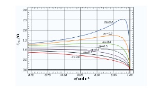
m-derived prototype shunt low-pass filter ZiTm image impedance for various values of m. Values below cut-off frequency only shown for clarity. The following expressions for image impedances are all referenced to the low-pass prototype section. They are scaled to the nominal impedance R0 = 1, and the frequencies in those expressions are all scaled to the cut-off frequency ωc = 1.
Series sections
The image impedances of the series section are given by
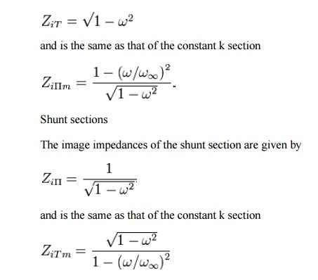
As with the k-type section, the image impedance of the m-type low-pass section is purely real below the cut-off frequency and purely imaginary above it. From the chart it can be seen that in the passband the closest impedance match to a constant pure resistance termination occurs at approximately m = 0.6
Transmission parameters
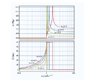
m-Derived low-pass filter transfer function for a single half-section
For an m-derived section in general the transmission parameters for a half-section are given by
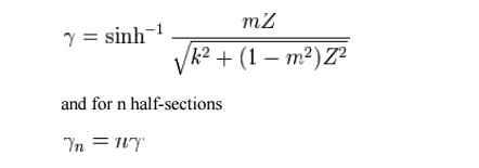
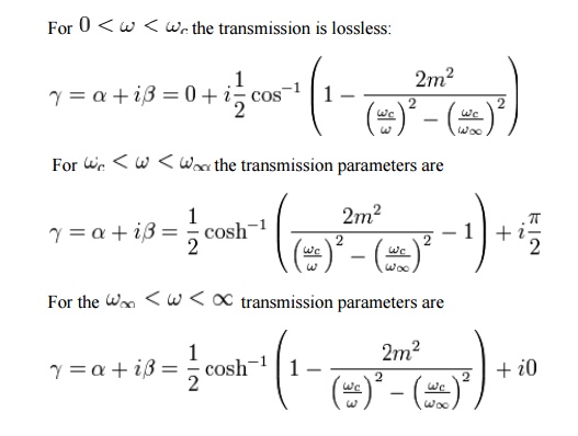
For the particular example of the low-pass L section, the transmission parameters solve differently in three frequency bands.
Related Topics