Microcontroller and Peripheral Interfacing Laboratory - EC25C14
[ 4th Semester - ECE - Electronics and Communication Engineering Department ]
Under Class: | 4th Semester [ECE Dept Anna University 2025 Regulation] |
Microcontroller and Peripheral Interfacing Laboratory - EC25C14 - Practical Manual, Experiments, Guide Study Materials PDF Download
Engineering - Microcontroller and Peripheral Interfacing Laboratory - EC25C14 Subject (under Anna University 4th Semester - ECE - Electronics and Communication Engineering Department Regulation 2025) - Practical Manual, Experiments, Guide Study Materials PDF Download
EC25C14:
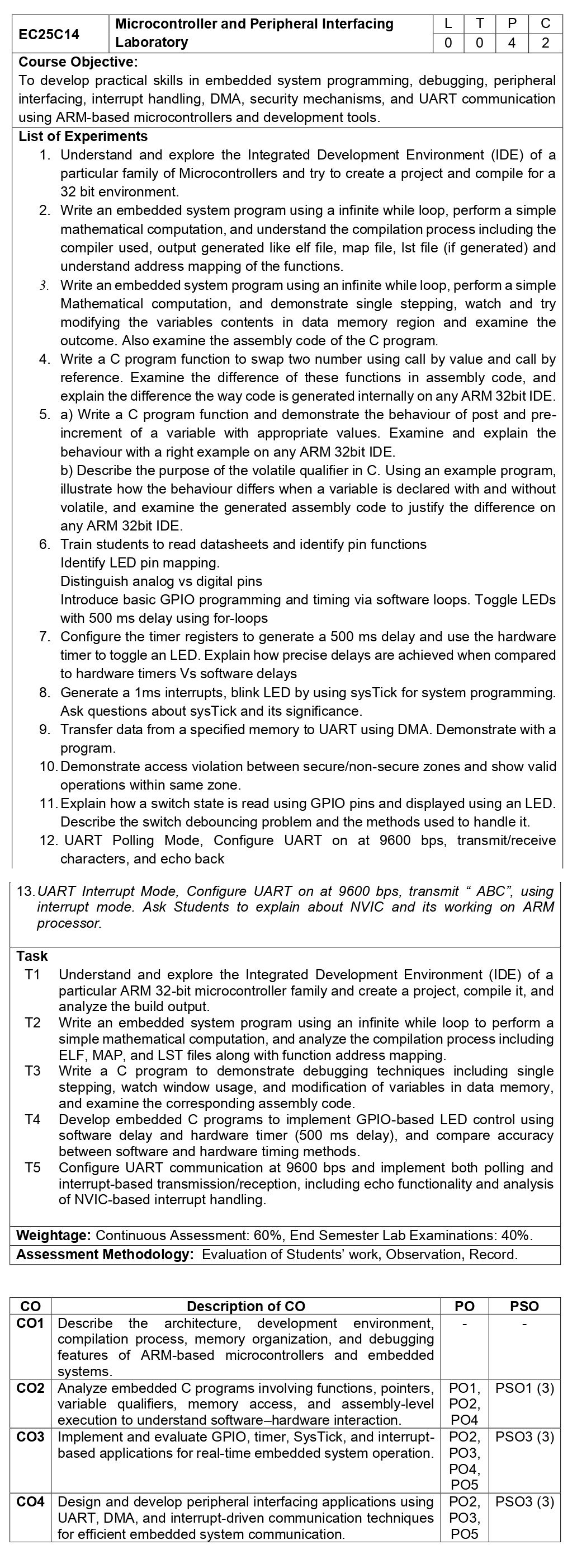
Microcontroller
and Peripheral Interfacing Laboratory
Course
Objective:
To
develop practical skills in embedded system programming, debugging, peripheral
interfacing,
interrupt handling, DMA, security mechanisms, and UART communication using
ARM-based microcontrollers and development tools.
List of
Experiments
1.
Understand and explore the Integrated Development Environment (IDE) of a
particular family of Microcontrollers and try to create a project and compile
for a 32 bit environment.
2.
Write an embedded system program using a infinite while loop, perform a simple
mathematical computation, and understand the compilation process including the
compiler used, output generated like elf file, map file, lst file (if
generated) and understand address mapping of the functions.
3.
Write an embedded system program using an infinite while loop, perform a simple
Mathematical computation, and demonstrate single stepping, watch and try
modifying the variables contents in data memory region and examine the outcome.
Also examine the assembly code of the C program.
4.
Write a C program function to swap two number using call by value and call by
reference. Examine the difference of these functions in assembly code, and
explain the difference the way code is generated internally on any ARM 32bit
IDE.
5.
a) Write a C program function and demonstrate the behaviour of post and
pre-increment of a variable with appropriate values. Examine and explain the
behaviour with a right example on any ARM 32bit IDE.
b)
Describe the purpose of the volatile qualifier in C. Using an example program,
illustrate how the behaviour differs when a variable is declared with and
without volatile, and examine the generated assembly code to justify the
difference on any ARM 32bit IDE.
6. Train students to read datasheets and identify pin functions Identify LED pin mapping. Distinguish analog vs digital pins Introduce basic GPIO programming and timing via software loops. Toggle LEDs with 500 ms delay using for-loops
7.
Configure the timer registers to generate a 500 ms delay and use the hardware
timer to toggle an LED. Explain how precise delays are achieved when compared
to hardware timers Vs software delays
8.
Generate a 1ms interrupts, blink LED by using sysTick for system programming.
Ask questions about sysTick and its significance.
9.
Transfer data from a specified memory to UART using DMA. Demonstrate with a
program.
10.
Demonstrate access violation between secure/non-secure zones and show valid
operations within same zone.
11.
Explain how a switch state is read using GPIO pins and displayed using an LED.
Describe the switch debouncing problem and the methods used to handle it.
12. UART Polling Mode, Configure UART on at 9600 bps, transmit/receive characters, and echo back
13.
UART Interrupt Mode, Configure UART on at 9600 bps, transmit “ ABC”, using
interrupt mode. Ask Students to explain about NVIC and its working on ARM
processor.
Task
T1
Understand and explore the Integrated Development Environment (IDE) of a
particular ARM 32-bit microcontroller family and create a project, compile it,
and analyze the build output.
T2
Write an embedded system program using an infinite while loop to perform a
simple mathematical computation, and analyze the compilation process including
ELF, MAP, and LST files along with function address mapping.
T3 Write
a C program to demonstrate debugging techniques including single stepping,
watch window usage, and modification of variables in data memory, and examine
the corresponding assembly code.
T4
Develop embedded C programs to implement GPIO-based LED control using software
delay and hardware timer (500 ms delay), and compare accuracy between software
and hardware timing methods.
T5
Configure UART communication at 9600 bps and implement both polling and
interrupt-based transmission/reception, including echo functionality and
analysis of NVIC-based interrupt handling.
Weightage:
Continuous Assessment: 60%, End Semester Lab Examinations: 40%.
Assessment Methodology:
Evaluation
of Students’ work, Observation, Record.