Chapter: Aquaculture Engineering : Design and Construction of Aquaculture Facilities
Water intake and transfer - Land-based hatchery, juvenile and on-growing production plant in Aquaculture Engineering
Water intake and transfer
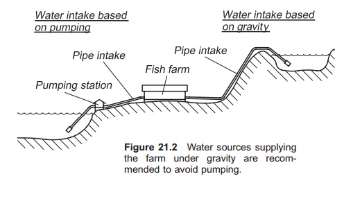
The design of the water intake and transfer system depends on whether the water source is at a higher altitude than the farm, so the water flows under gravity into the farm, or whether the source is on the same or at a lower level than the farm, so that pumping of the inlet water is necessary. If possible, the first alternative is of course recommended (Fig. 21.2).
Transfer pipes can be quite large, and therefore expensive, so it is recommended to have as short a distance from the water source to the farm as pos-sible. If the distance is more than 500 m the cost of the inlet pipe will be considerable. Hence land-based fish farms should be located as close tothe water source as possible. The same is of course the case for the distance between the farm and the recipient water body, if the water is to be trans-ported through a pipeline.
If the water is to be pumped into the farm, a high lift head is not recommended because this increases the pumping costs; heads 10–15 m will result in quite large costs. If such conditions prevail, the case for increased oxygenation and use of recycling systems must be evaluated, to reduce the amount of water needed and hence reduce the operating costs of the farm.
Water inlet
The inlet design depends on the source: lake, river, groundwater or the sea.
Lake: In lakes deeper than 10–20 m there is nor-mally thermal stratification. The ratio between the water temperature and the water density causes this stratification. Because water is most dense at 4°C, water at this temperature will sink to the bottom and warmer water will float on top. In areas where the water temperature falls below 4°C in the winter, there will be mixing of water during spring and autumn. In the autumn, the surface tempera-ture is reduced; when it reaches 4°C mixing will occur because all the water will have the same density and only a slight breeze on the surface will ensure mixing. Strong winds may also result in mixing of water in the column at other times of the year.
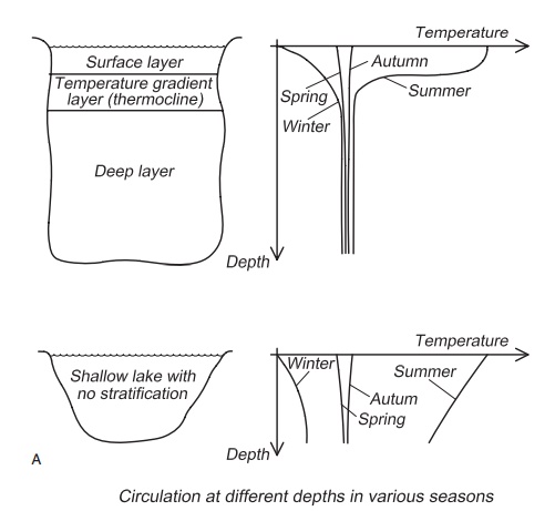
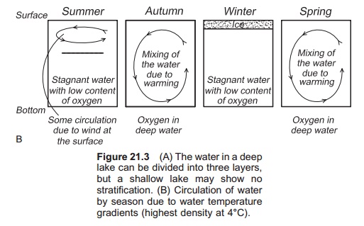
It is normal to divide the water column into three layers, the surface layer (epilimnion), a layer with a steep temperature gradient where a large differ-ence in temperature occurs (metalimnion), and the bottom layer (hypolimnion) (Fig. 21.3). The depth at which the steepest temperature increase/ decrease occurs is known as a thermocline. Water collected from below this depth is said to have been collected below the thermocline. If there is such a layer in the lake it is recommended that the inlet be sited below the thermocline to avoid tempera-ture variations that are large and difficult to control. Two intakes can be installed, one above and one below the thermocline, so that the warm surface water can be used to increase fish growth, but then possible problems with fouling must be taken into account.
In a lake the inlet pipe is normally laid on the bottom. The pipe must be correctly aligned, and large stones and deep cracks avoided; regular sloping of the bottom is advantageous. Under watercameras or an echo sounder should be used to align the pipe before it is fixed in position with weights. These are normally concrete blocks clamped to the pipe; the distance between them depends on the pipe size and water flow.
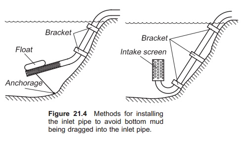
The actual inlet ought to be placed some distance from the bottom to avoid mud and small stones being sucked into the inlet pipe. This can be achieved in different ways, for instance by adding a float at the end of the pipe or by using an elbow that directs the pipe upwards in the water column (Fig. 21.4). To avoid fish and other large substances being dragged into the inlet pipe, a screen is used at the orifice. The water velocity through the screen must not be too large to prevent small fish and other objects getting sucked onto the surface of the screen and blocking the inlet. Water inlet velocities of less than 0.1 m/s are recommended, while in the inlet pipe itself flows of 1–1.5 m/s are used. Poly-ethylene (PE) has proved to be a suitable material for inlet pipelines, because it is both reasonably priced and to some extent will follow the contours of the terrain.
Sea: In the sea the same principles for an inlet in alake are used. However, the thermocline is normally located deeper in the sea, normally from 30 to 70 m. Here also it is advantageous to have the inlet below the thermocline. The water tempera-tures will then be predictable, at least when the farm has been in use for some years, or if much historical data are available. For future production planning predictable temperatures are a great advantage but predicting surface water temperature is impossible. Another great disadvantage with having the water inlet above the thermocline and close to the surface is the problem of fouling inside the pipe. With high water temperatures, the inlet pipe will become totally fouled quite quickly and the water flow will be dramatically reduced. Facilities to clean the inlet pipe must, in such cases, be an integral part of the construction.
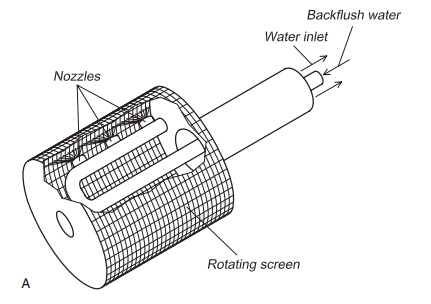
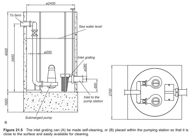
For water inlets at great depths, it will be difficult to clean the grating if it becomes blocked, so self-cleaning inlet gratings should be used (Fig. 21.5). Another, and probably a better solution, is to place the grating in the pumping station near the surface instead of end of the inlet pipe. The inlet pipe is now completely open at the bottom; objects will be swept in with the water but are stopped by the grating in the pumping station. A funnel at the start of the inlet pipe may also be used. This will reduce the water velocity and at the same time the resistance head. In the pumping station it will be quite easy to inspect the grating visually and remove accumulated debris.
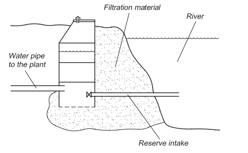
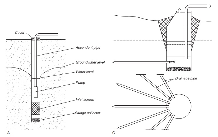
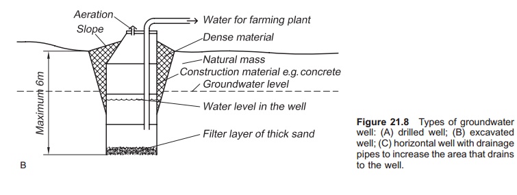
An infiltration intake may also be used if ground conditions are suitable. As for infiltration inlets from rivers described below (Fig. 21.6), various designs of the inlet are possible. For example, a well can be built on the beach but the beach mate-rial must be sufficiently permeable.
The cost of inlet pipes in the sea can be considerable, because they must be long enough to reach adequate depth and be below the thermocline; a good site therefore has a short distance to the acceptable depth, so deep water close to the shore is advantageous. A site on a long shallow coastline is normally poor.
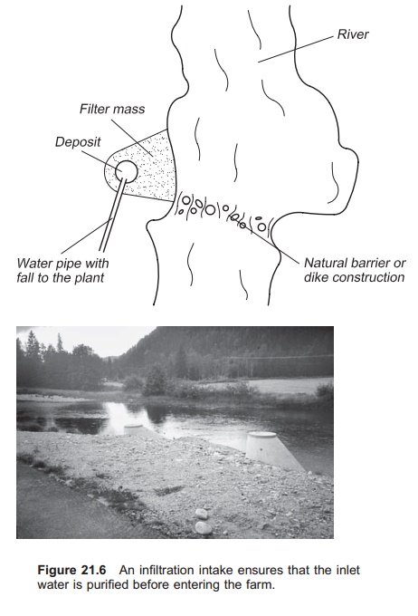
River: When the inlet source is a river, the location of the inlet is very important. Rivers normally transport a lot of suspended particles and larger objects that are unwanted in the inlet water to the fish farm. The autumn period is especially critical when a lot of fallen leaves are transported in the water. Flood situations will also be critical because the amount of suspended particles in the water increases due to erosion. The inlet ought therefore to be laid in an area were the velocity of the river
Pumping station
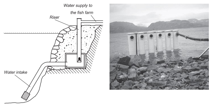
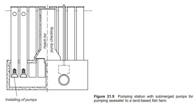
If pumps are used to transfer water to the farm a pumping station is needed. The pumps are either dry placed or submerged. Special equipment is necessary to make dry-placed pumps self-priming if the pump is installed at a higher level than the seawater. If such pumping stations are used, special care must be taken to avoid sucking of ‘false air’. Dry-placed pumps may be installed in a well where there is pressure from the water, so circumventing this problem; this specially designed well must, in these cases, be excavated and cast. Submerged pumps will always be placed in some type of well (Fig. 21.9); both propeller and centrifugal pumps can be used. Propeller pumps are recommended with large water flows and low lift height (below 10 m). If submerged pumps are used, the shore where the pumping station is to be placed must be shielded from the waves. It is also recommendedthat areas with large waves are avoided when siting pipes to dry-placed pumping stations. There are also experiences with drilling the inlet pipe in rock and siting the entire pumping station inside a mountain.The pumping station can also be placed on the seashore and water is lead into the station through pipes. This requires appropriate ground conditions, sand or gravel for example.
For emergency reasons, the water should be sup-plied to a farm using at least two pumps. It is important that the total efficiency of the pumps is high to reduce the cost per cubic metre of water. If the requirements for water delivery vary, it could be advantageous to use several pumps of different size; however standardization of the pumps so that it is possible to change spare parts and have a common stock of the most needed spares, will be difficult in such cases. There should be at least one stand-by pump in the pumping station. A pro-gramme that alternates between the pumps should be used so that all pumps will be run for some period. In this way the stand-by pump is always in use and not found to have seized up with rust when needed.
The pumps are installed in a pumping station.
Dry-placed pumps are placed in a building on shore. For submerged or dry-placed pumps in a well, the pumping station is placed below the low tide mark in the sea. The pumping station is often made of prefabricated concrete or fibre glass. Sub-merged pumps should be placed on guide rails so that is easy to take them up for maintenance.
Transfer pipeline
As mentioned earlier, transfer pipes should be as short as possible to avoid unnecessary expense. If only a low head is available (<5 m) or if the water is pumped, it is especially important to use piping that is as smooth as possible. Single resistances with high friction coefficients must be avoided; 90° elbows should be substituted with shallower bends, for instance three 30° elbows, or one long smooth elbow. Reduced velocity through the pipelines could also be used to reduce the friction loss, but it must be above 0.5 m/s to avoid settling.
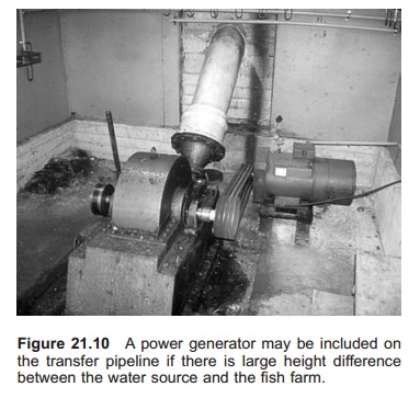
If the water source is at a sufficiently higher altitude than the farm (>30 m) the water velocity in the pipeline could be very high; velocities above 3 m/s should be avoided to prevent breakage in the water column and vacuum effects. Increased velocities will also increase the requirements for anchoring the pipes. In such circumstances a small generator can be installed to utilize the energy in the inlet water (Fig. 21.10); it is important to choose one made of material that is not toxic to the fish. After the turbine, it is important to aerate the water to avoid possible supersaturation with nitrogen gas.
Care must be taken if the pipe is laid over a hill or ridge (high crest) from a lake and is functioning as a siphon (Fig. 21.11) because a vacuum effect will
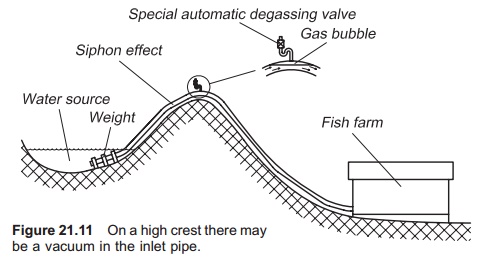
occur on the top crest and the pipe may collapse. To avoid this, it is important to use a pipe of a sufficiently high pressure class which has a thick wall. Another problem that may occur when the pipeline is not evenly sloped in one direction, is the creation of gas bubbles at the crests. Normally there will always be some gas bubbles in the water and they will collect at the crests; when numerous bubbles collect at this point the effective cross-sectional area of the pipe is reduced. This will again reduce the water flowing through the pipe and in the worst case the water flow can be totally blocked by the gas bubble. The use of a siphon on the inlet pipe is therefore not optimal, and if possible should be avoided. Instead of laying the pipe across the shore of a lake it may be advantageous to excavate a channel out of the lake in which the pipe is placed. It is also important that the pipe is laid with a good and even slope.
If there are possibilities for gas collection at points in the transfer pipeline or pipelines inside the farm, special degassing valves can be used. These can be automatic and discharge gas when necessary. Degassing can also be done manually by installing a valve at the critical point in the pipeline and open it at fixed intervals. It should be remem-bered that there must be pressure in the system when the valve is opened to force the gas out. The valve can be closed as soon as the water comes out. In a siphon construction a special valve must be used to avoid breaking the siphon.
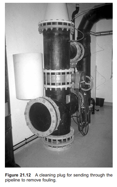
If fouling occurs in the inlet pipeline, it can be cleaned out by sending plugs through the inlet pipe, which is known as plugging. The cleaning plug can be inserted at the start of the inlet pipe and with-drawn at a point inside the farm (Fig. 21.12). The plug can, for instance, be made of some type of foam rubber. It is important to have enough water pressure to force the plug through the transfer pipeline.
Related Topics