Chapter: Flexible Alternating Current Transmission System : Emerging FACTS Controllers
Unified Power Flow Controller (UPFC): Principle, Modes of Operation and Applications
UNIFIED POWER FLOW CONTROLLER
(UPFC)
UPFC is a
combination of STATCOM and SSSC coupled via a common DC voltage link.
1. Principle of Operation
Ø The UPFC
is the most versatile FACTS controller developed so far, with all encompassing
capabilities of voltage regulation, series compensation, and phase shifting.
Ø It can
independently and very rapidly control both real- and reactive power flows in a
transmission.
Ø It is
configured as shown in Fig. and comprises two VSCs coupled through a common dc
terminal.
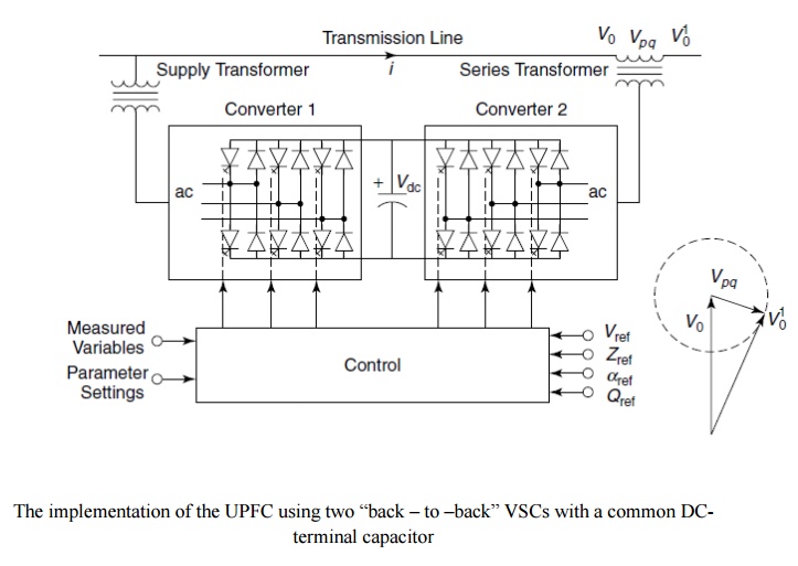
The implementation of the UPFC using two “back – to
–back” VSCs with a common DC-terminal capacitor
Ø One VSC
converter 1 is connected in shunt with the line through a coupling transformer;
the other VSC converter 2 is inserted in series with the transmission line
through an interface transformer.
Ø The dc
voltage for both converters is provided by a common capacitor bank.
Ø The
series converter is controlled to inject a voltage phasor, Vpq, in series with the line, which can be varied from 0 to Vpq max. Moreover, the phase angle of Vpq can be independently varied from 00
to 3600.
Ø In this
process, the series converter exchanges both real and reactive power with the
transmission line.
Ø Although
the reactive power is internally generated/ absorbed by the series converter,
the real-power generation/ absorption is made feasible by the dc-energy–storage
device that is, the capacitor.
Ø The
shunt-connected converter 1 is used mainly to supply the real-power demand of
converter 2, which it derives from the transmission line itself. The shunt
converter maintains constant voltage of the dc bus.
Ø Thus the
net real power drawn from the ac system is equal to the losses of the two
converters and their coupling transformers.
Ø In
addition, the shunt converter functions like a STATCOM and independently
regulates the terminal voltage of the interconnected bus by generating/
absorbing a requisite amount of reactive power.
2. Modes of Operation
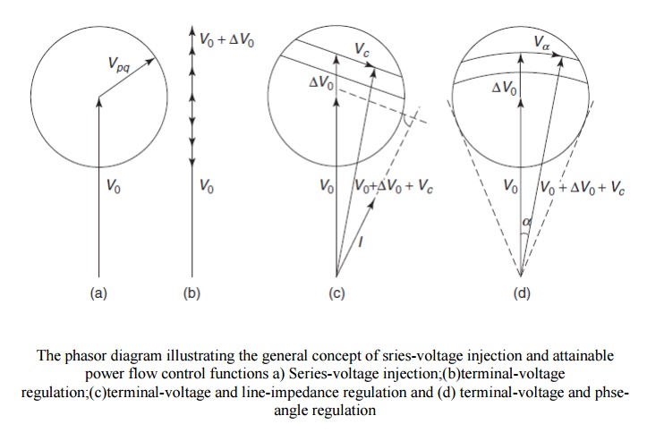
The
phasor diagram illustrating the general concept of sries-voltage injection and
attainable power flow control functions a) Series-voltage
injection;(b)terminal-voltage regulation;(c)terminal-voltage and line-impedance
regulation and (d) terminal-voltage and phse-angle regulation
The
concepts of various power-flow control functions by use of the UPFC are
illustrated in Figs. 10.26(a)–(d). Part (a) depicts the addition of the general
voltage phasor Vpq to the existing
bus voltage, V0, at an angle that
varies from 00 to 360 0.
Ø Voltage
regulation is effected if Vpq =∆V0 is generated in phase with V0, as shown in part (b). A combination
of voltage regulation and series compensation is implemented in part (c), where
Vpq is the sum of a voltageregulating
component ∆V0 and a series
compensation providing voltage component Vc
that lags behind the line current by 900. In the phase-shifting process
shown in part (d), the UPFC-generated voltage Vpq is a combination of voltage-regulating component ∆V0 and phase-shifting voltage component Va.
Ø The
function of Va is to change the phase
angle of the regulated voltage phasor, V0
+ ∆V, by an angle α. A simultaneous
attainment of all three foregoing power-flow control functions is depicted in
Fig.
Ø The
controller of the UPFC can select either one or a combination of the three
functions as its control objective, depending on the system requirements.
Ø The UPFC
operates with constraints on the following variables :
1. The
series-injected voltage magnitude;
2. The line
current through series converter;
3. The
shunt-converter current;
4. The
minimum line-side voltage of the UPFC;
5. The
maximum line-side voltage of the UPFC; and
6. The
real-power transfer between the series converter and the shunt converter
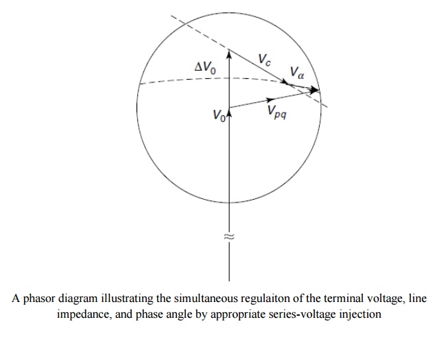
A phasor
diagram illustrating the simultaneous regulaiton of the terminal voltage, line
impedance, and phase angle by appropriate series-voltage injection
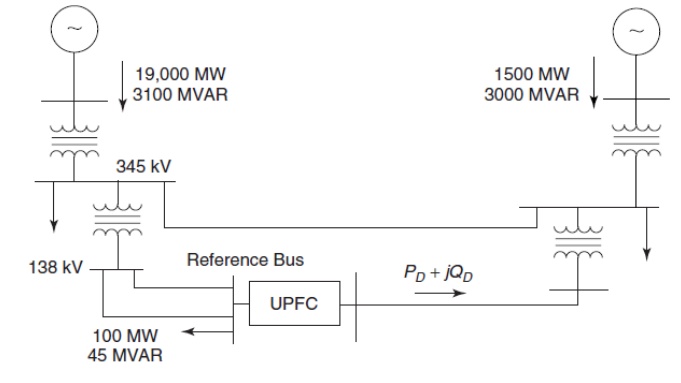
3. Applications (UPFC)
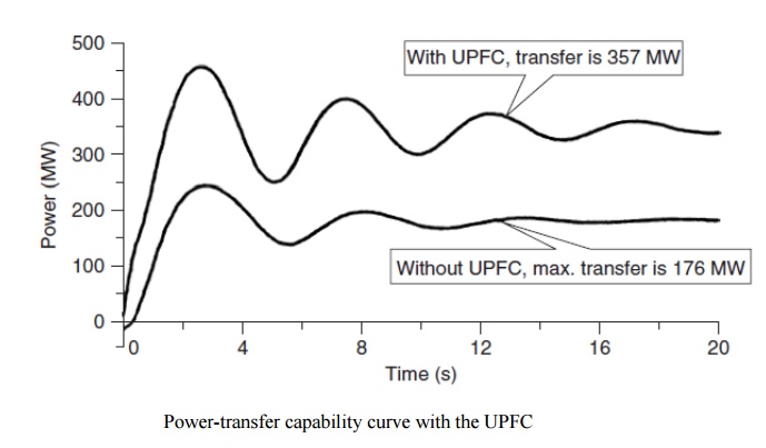
Ø The
power-transmission capability is determined by the transient-stability
considerations of the 345-kV line.
Ø The UPFC
is installed in the 138-kV network. A 3-phase-to-ground fault is applied on the
345-kV line for four cycles, and the line is disconnected after the fault.
Ø The
maximum stable power flow possible in the 138-kV line without the UPFC is shown
in Fig. to be 176 MW.
Ø However,
the power transfer with the UPFC can be increased 181 MW (103%) to 357 MW.
Although this power can be raised further by enhancing the UPFC rating, the
power increase is correspondingly and significantly lower than the increase in
the UPFC rating, thereby indicating that the practical limit on the UPFC size
has been attained.
Ø The UPFC
also provides very significant damping to power oscillations when it operates
at power flows within the operating limits.
Ø The UPFC
response to a 3-phase-line-to-ground fault cleared after four cycles, leaving
the 345-kV line in service, is illustrated in Fig. Because the 345-kV line
remains intact, the oscillation frequency changes from that shown in Fig.
4. Modeling of UPFC for power
flow studies
The
steady state investigation of UPFC involves power flow studies which include
the calculation of busbar voltage, branch loadings, real and reactive
transmission losses and the impact of UPFC.
Ø In this
model two voltage sources are used to represent the fundamental components of
the PWM controlled output voltage waveform of the two branches in the UPFC.
Ø The
impedance of the two coupling transformers are included in the proposed model
and the losses of UPFC deppicts the voltage source equivalent circuit of UPFC.
Ø The
series injection branch a series injection voltage source and performs the main
functions of controlling power flow whilst the shunt branch is used to provide
real power demanded by the series branch and the losses in the UPFC.
Ø However
in the proposed model the function of reactive compensation of shunt branch is
completely neglected.
Related Topics