Chapter: Mechanical : Strength of Materials : Thin Cylinders, Spheres and Thick Cylinders
Thin Cylinders, Spheres and Thick Cylinders
THIN CYLINDERS, SPHERES AND THICK CYLINDERS
Triaxial
Stress, Biaxial Stress, and Uniaxial Stress
Triaxial stress refers
to a condition where only normal stresses act on an element and all shear
stresses (txy, txz, and tyz) are zero. An
example of a triaxial stress state is hydrostatic pressure acting on a small
element submerged in a liquid.
A two-dimensional state of stress in which only two
normal stresses are present is called biaxial stress. Likewise, a
one-dimensional state of stress in which normal stresses act along one
direction only is called a uniaxial stress state.
Pure
Shear
Pure shear refers to a stress state in which an
element is subjected to plane shearing stresses only, as shown in Figure 3.
Pure shear occurs in elements of a circular shaft under a torsion load.
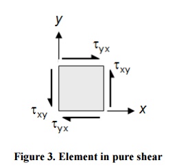
Figure
3. Element in pure shear
Thin
cylindrical and spherical shells
Thin-walled
assumption
For the thin-walled assumption to be valid the
vessel must have a wall thickness of no more than about one-tenth (often cited
as one twentieth) of its radius. This allows for treating the wall as a
surface, and subsequently using the Young–Laplace equation for estimating the hoop stress created by an
internal pressure on a thin wall cylindrical pressure vessel:
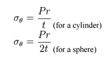
where
·
P is
the internal pressure
·
t is
the wall thickness
·
r is
the inside radius of the cylinder.
·
Ro Deta is the hoop stress.
The hoop stress equation for thin shells is also
approximately valid for spherical vessels, including plant cells and bacteria
in which the internal turgor pressure
may
reach several atmospheres.
Inch-pound-second system (IPS) units for P
are pounds-force
per square inch (psi). Units for t, and d
are inches (in). SI units for P are pascals
(Pa), while t and d=2r are in meters (m).
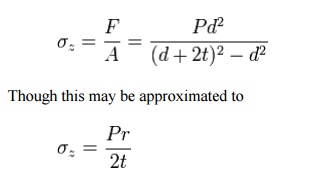
When the vessel has closed ends the internal
pressure acts on them to develop a force along the axis of the cylinder. This
is known as the axial stress and is usually less than the hoop stress.
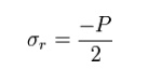
Also in this situation a radial stress is developed and may be estimated in thin
walled cylinders as:
Deformation
in thin cylindrical and spherical shells
Thick
cylinders and shells
Thick
Walled Cylinders
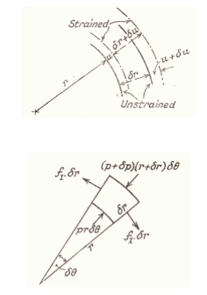
Under the action of radial Pressures at the
surfaces, the three Principal Stresses will be . These Stresses may be expected
to vary over any cross-section and equations will be found which give their
variation with the radius r.
It is assumed that the longitudinal Strain e is
constant. This implies that the cross-section remains plain after straining and
that this will be true for sections remote from any end fixing.
Let u be the radial shift at a radius r. i.e. After
Straining the radius r becomes (r + u). and it should be noted that u is small
compared to r.
Internal Pressure Only
Pressure Vessels are found in all sorts of
engineering applications. If it assumed that the Internal and Pressure is at a
diameter of that the external pressure is zero ( Atmospheric) at a diameter
then using equation (22)
The Error In The "thin
Cylinder" Formula
If the thickness of the cylinder walls is t then and
this can be substituted into equation
Which
is 11% higher than the mean value given by And if the ratio is 20 then which is
5% higher than
It
can be seen that if the mean diameter is used in the thin cylinder
formula, then the error is minimal.
Example
1
The cylinder of a Hydraulic Ram has a 6 in. internal
diameter. Find the thickness required to withstand an internal pressure of 4
tons/sq.in. The maximum Tensile Stress is limited to 6 tons/sq.in. and the
maximum Shear Stress to 5 tons/sq.in.
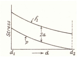
If
D is the external diameter, then the maximum tensile Stress is the hoop Stress
at the inside.
Using equation (43)
Stresses
on inclined plane
Stresses
on inclined plane
procedure
to tackle stresses on inclined planes
STEPS:
In
order to do achieve the desired objective we proceed in the following manner
(i) Label
the Block ABCD.
(ii) Set
up axes for the direct stress (as abscissa) and shear stress (as ordinate)
(iii) Plot
the stresses on two adjacent faces e.g. AB and BC, using the following sign
convention.
tensile positive; compressive, negative Shear
stresses –tending to turn block clockwise, positive
–tending to turn block counter clockwise, negative
[ i.e shearing stresses are +ve when its movement
about the centre of the element is clockwise ]
This gives two points on the graph which may than be
labeled as respectively to denote stres
these planes.
(iv) Join AB bar and BC bar.
(v) The point P
where this line cuts the s axis is than the centre of Mohr's stress circle and
th joining AB bar and BC bar is diameter. Therefore the circle can now be
drawn.
Now every point on the circle then represents a
state of stress on some plane through C.
Principal
planes and stresses
Principal stresses and planes
Principal Directions, Principal Stress
x' andy' (x'y') vary smoothly with respect to the
rotation accordance with the coordinate
transformation equations. There exist a couple of particular angles wher take
on special values.
First, there exists an angle p where the shear
stress x'y' becomes zero. That angle is found by setting the above shear
transformation equation and solving for (set equal to p). The result is,
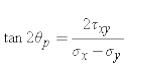
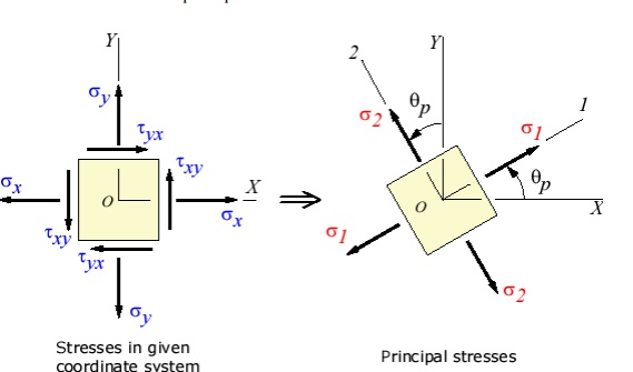
The angle p defines the principal directions where
the only stresses are normal stresses. These called principal stresses and are
found from the original stresses (expressed in the x,y,z directions) via,
The transformation to the principal directions can
be illustrated as:
Maximum Shear Stress Direction
s, is where the maximum shear stress occurs. This is
found by finding the ma. Another important angle, shear stress transformation
equation, and solving for

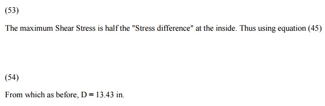
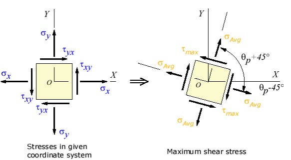
The maximum shear stress is equal to one-half the
difference between the two principal stresses,
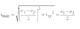
The transformation to the maximum shear stress
direction can be illustrated as:
Mohr’s
circle for biaxial
stress
To find the maximum and
minimum normal stresses throughout the entire range of angles, one can easily
take the first derivative of (3) with respect to theta, set it to zero, and
solve for the angle. This will give what is called the principal plane
on which the principal
stresses act.
If this all sounds overly complicated... you're right! Why not just use the
tried and true terminology "maximizing and minimizing the
function" instead of inventing these two new terms with unrelated and
unclear meaning? Well.... that's civil engineers for you.
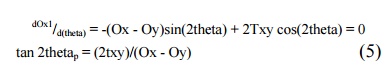
Where thetap defines the orientation of the principal planes, and its two
values, differing by 180o, are called the principal angles.
Now is where we begin to get into the unnecessary jargon. All the excess
baggage some engineer created to make it so that utilizing these relationships
would not require higher math. This (and many other examples of engineer
idioticy) most likely stems from the fact that most engineers slept through
their higher level math classes, and suffer from acute mathematical
insecurities (and probably rightly so.) It's these abstract constructions which
attempt to simplify the work, yet ultimately make it more difficult for those
of us more mathematically inclined, that really piss me off. If you represent
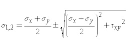
equation (5) geometrically with a 90o triangle, (left), we can obtain general
formulas for the principal stresses. First, we note that the hypotenuse of the
triangle is,
R = SQR{ [(Ox - Oy)/2]2
+ Txy2} (6)
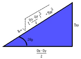
The quantity R is defined as a positive number, and, like the other two
sides of the triangle, has the completely meaningless units of
"stress". From the triangle we obtain two additional relations:
cos(2thetap)
= (Ox - Oy)/(2R) sin(2thetap)
= Txy/R (7, 8)
Which is all very well
and good, because it actually leads to the USEFUL equation for the general
formula for the principal stresses:
O1,2 = (Ox +
Oy)/2 +/- R (9)
But such usefulness is
short lived as we approach MOHR'S CIRCLE..... Actually, Mohr's circle isn't all
that bad in many cases. It supplies its practitioners a clever and easy way to
compute otherwise hairy moments of inertia, allows strain analyses to be
handled quickly. However, in this case, its application seems to me a bit of a
stretch, and what you wind up with is this hopelessly complicated graphical
representation that seems so much more difficult than the original equations
(3) and (4) that it's hardly worth the effort to learn at all. HOWEVER....
because certain bastich
elements in the civil engineering department here at
the U of A
are requiring their students (many of whom, myself included, will NEVER use
these relationships again after the class has ended) to use this technique in
spite of the fact that we know of a perfectly valid and correct alternative.
The equations of Mohr's
circle can be derived from the transformation equations (3) and (4). By simply
rearranging the first equation, we find that the two expressions comprise the
equation of a circle in parametric form.
Ox1 - (Ox +
Oy)/2 = [(Ox - Oy)/2]cos(2theta) + Txy sin(2theta) (10)
Tx1y1
= - {(Ox - Oy)/2}sin(2theta) + Txy cos(2theta)
(11)
To eliminate the 2theta
parameter, we square each relationship and add the two equations together. This
ultimately leads to (after simplification),
(Ox1 - {Ox +
Oy}/2)2 + Tx1y12 = {(Ox - Oy)/2}2
+ Txy2 (12)
However, by
resubstitution of equation (6) and by recognizing that the average stress value
between the X and Y axis, Oave, is,
Oave = (Ox + Oy)/2
equation (12) can be
simplified into the semi friendly equation of a circle in standard algebraic
form,
(Ox1 - Oave)2
+ Tx1y12 = R2 (13)
However, don't let this
nice looking equation for a circle fool you. Hidden in this simple equation are
some of the most hairy, complicated, and down-right nasty relationships I think
I have ever encountered. This makes my studies in the Frobenious theorem for
solving differential equations with non-constant singular coefficients seem
tame.
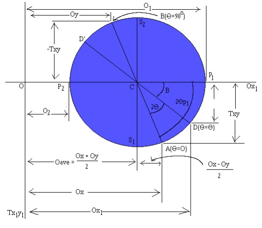
With Ox, Oy, and Txy
known, the procedure for constructing Mohr's circle is as follows:
1. Draw
a set of coordinate axis with Ox1 and Tx1y1
(with T positive downwards. From now on, for simplicity, O and T will represent
their respective axis.)
2. The
center of the circle, by equation (13) is located at T=0 and O=Oave. Oave is
nothing more than (12.a), so the center of the circle is located at:
C
= (Ox + Oy)/2
3. Locate
point A, representing the stress conditions on the X face of the normal
oriented element (Figure 1, extreme top left, non-rotated section). Plot
coordinates O = Ox, T = Txy. Here, it is important to note that at point A, the
inclination angle, theta, is zero.
4. Locate
point B, representing the stress conditions on the Y face of the normal
oriented element (Figure 1, again, extreme top left, non-rotated section).
Again, plot
coordinates O = Oy, T = Txy. Note that this point,
B, will be diametrically opposite from point A. Also note, that the angle of
inclination at B, theta, will be 90o, as it could also be achieved
on the X face by rotating it by 90o.
5. Draw
a line from point A to point B through the center C. This line is a diameter of
the circle.
6.
Using point C as the center, draw Mohr's
circle through points A and B. The circle will have a radius of R, which is the
same R as in equation (6).
Now that you have
Mohr's circle drawn, you can use it to analyze the problem. (Remember, that
this method is every bit as valid as simply using equations (3) and (4) above,
except it requires less mathematical skill, and many more memorized
relationships.)
O1,2,
representing the maximum and minimum normal stresses and their respective
angles away from point A (where theta = 0o) can be found by simply
looking at the O values when T = 0. In the drawing above, O1
represents the maximum, and O2 the minimum.
Furthermore, Tmax/min,
representing the maximum and minimum shear stresses and their respected angles
can be found by locating the T values when O = Oave. At this point, T is
simply equal to the radius, R, or equation (6).
In addition to these
helpful points, all other possible points for the shear and normal stresses can
be found on this circle. In order to find another value of Ox, Oy for a given
rotation, one must simply start at the A and B points (A representing the Ox value
and B, the Oy value), and rotate in a positive theta direction (by the
orientation shown above, this is in a counterclockwise direction, in keeping
with the right hand rule) for 2theta (from equations
(3) and (4) above). The
resulting points, D and D', will yield the Ox, Txy, and Oy, Txy (respectively)
for that rotation.
As I have likely
mentioned before (likely because, I can't really recall) to me this seems all
very abstract and difficult to use. However, the aforementioned bastiches will
be requiring this on my upcoming test, so I felt a need to more fully
understand it. Granted, I still don't understand it as fully as I would hope,
but it ought to be enough to get me through this one, insignificant little
test.
P.S.: I apologize for
my editorializing and opinionated presentation of this topic. I rarely do this
when I analyze problems I don't understand (even when I do not like the method,
such as the Lewis Dot
structure). This time, however, I have some very
strong feelings about my predicament. Also, in all fairness, if you were given
the problem where O1 = O2 and Tmax = 0, i.e. the Mohr's circle was simply a
little dot with R = 0, using the Mohr's circle method would arrive you at any
and all answers much quicker than using equations (3) and (4). However, I don't
think this extreme simplification of one special case warrants the abstraction
being a required bit of knowledge for civil engineers.
Related Topics