Chapter: Digital Communication : Sampling & Quantization
Pulse code Modulation(PCM)
Pulse code Modulation:
The pulse code modulator technique samples the input signalx(t) at a sampling frequency. This sampled variable amplitude pulse is then digitalized by the analog to digital converter. Figure.shows the PCM generator.
The signal is first passed through sampler which is sampled at a rate of (fs)
where:
The output of the sampler x(nTs) which is discrete in time is fed to a „q‟ level quantizer. The quantizer compares the input x(nTs) with it's fixed levels. It assigns any one of the digital level to x(nTs) that results in minimum distortion or error. The error is called quantization error, thus the output of the quantizer is a digital level called q(nTs). The quantized
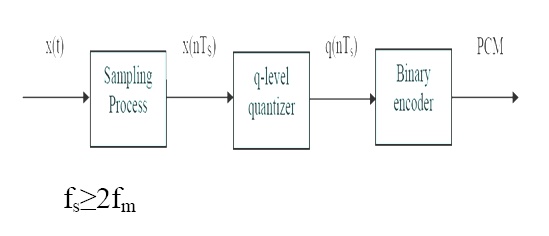
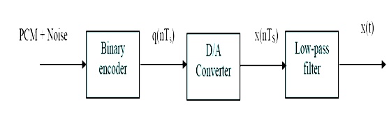
signal level q(nTs) is binary encode. The encoder converts the input signal to v digits binary word.The receiver starts by reshaping the received pulses, removes the noise and then converts the binary bits to analog.
The received samples are then filtered by a low pass filter; the cut off frequency is at fc.
fc= fm.
It is impossible to reconstruct the original signal x(t) because of the permanent quantization error introduced during quantization at the transmitter. The quantization error can be reduced by the increasing quantization levels. This corresponds to the increase of bits persample(more information). But increasing bits (v) increases the signaling rate and requires a large transmission bandwidth. The choice of the parameter for the number of quantization levels must be acceptable with the quantization noise (quantization error).
Signaling Rate in PCM
Let the quantizer use 'v' number of binary digits to represent each level. Then the number of levels that can be represented by v digits will be : q=2v
The number of bits per second is given by : (Number of bits per second)=(Number of bits per samples)x(number of samples per second) = v (bits per sample) x fs (samples per second).
The number of bits per second is also called signaling rate of PCM and is Signaling rate= vfs
Quantization Noise in PCM System
Errors are introduced in the signal because of the quantization process. This error is called "quantization error".
ε= xq (nTs)- x(nTs)
Let an input signal x(nTs) have an amplitude in the range of xmax to - xmax The total amplitude range is : Total amplitude = xmax-(- xmax)=2 xmax
If the amplitude range is divided into 'q' levels of quantizer, then the step size 'Δ'. Δ= q/2 X max If the minimum and maximum values are equal to 1,xmax,=1,
- xmax=-1, Δ= q/2.
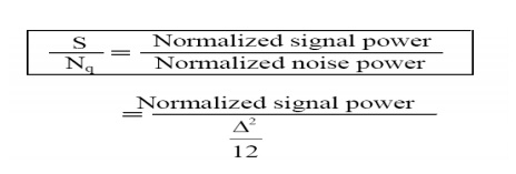
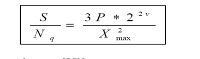
Signal to Quantization Noise ratio in PCM
The signal to quantization noise ratio is given as
The number of quantization value is equal to: q=2v
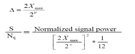
Let the normalized signal power is equal to P then the signal to quantization noise will be given by:
Advantages of PCM
1. Effect of noise is reduced.
2. PCM permits the use of pulse regeneration.
3. Multiplexing of various PCM signals is possible.
Related Topics