Chapter: Microprocessor and Microcontroller : Peripheral Interfacing
Programmable Interrupt Controller (8259): Features,Pinout, Block diagram
Programmable
Interrupt Controller (8259)
1 Features
ü 8 levels of interrupts.
ü Can be cascaded in master-slave configuration to handle 64 levels of interrupts.
ü Internal priority resolver.
ü Fixed priority mode and rotating priority mode.
ü Individually maskable interrupts.
ü Modes and masks can be changed dynamically.
ü Accepts IRQ, determines priority, checks whether incoming
priority > current level being serviced, issues interrupt signal.
ü In 8085 mode, provides 3 byte CALL instruction. In 8086 mode,
provides 8 bit vector number.
ü Polled and vectored mode.
ü Starting address of ISR or vector number is programmable.
ü No clock required.
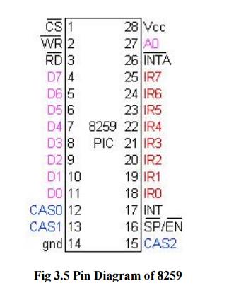
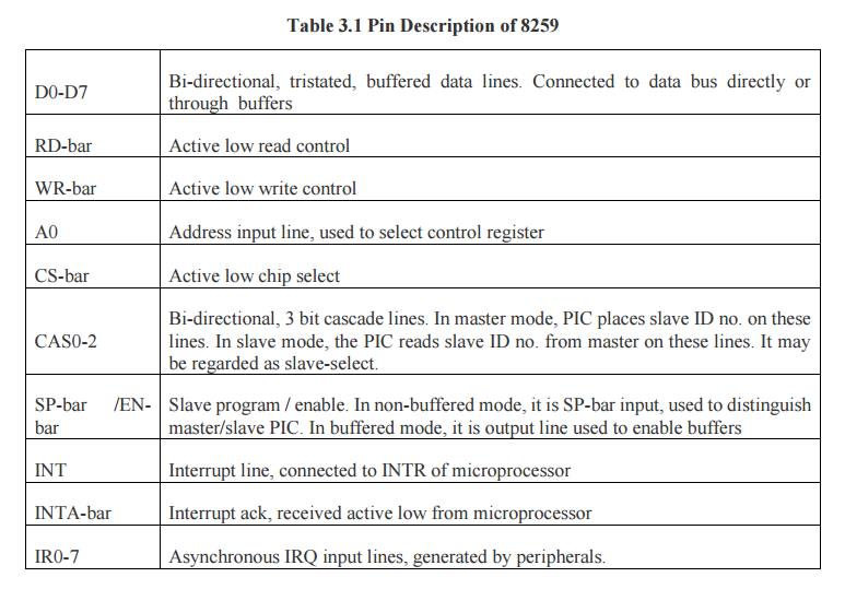
2 Pinout
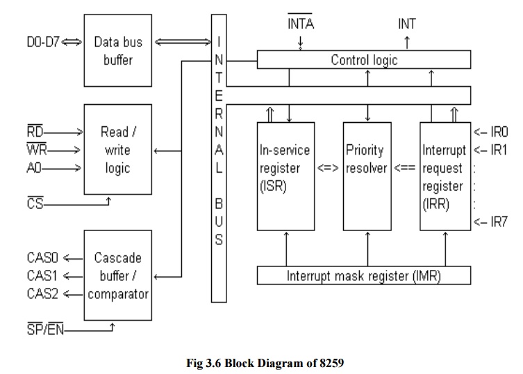
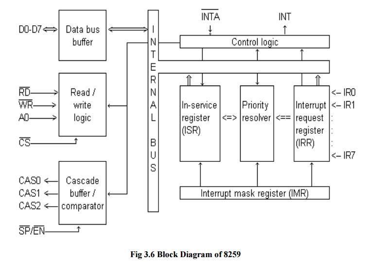
3 Block diagram
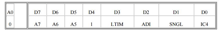
ü D0: IC4:
0=no ICW4, 1=ICW4 required
ü D1: SNGL:
1=Single PIC, 0=Cascaded PIC
ü D2: ADI: Address interval. Used only in 8085, not 8086. 1=ISR's are 4 bytes apart (0200, 0204, etc) 0=ISR's are 8 byte apart (0200, 0208, etc)
ü D3: LTIM: level triggered interrupt mode: 1=All IR lines level triggered. 0=edge triggered D4-D7: A5-A7: 8085 only. ISR address lower byte segment.
The lower
byte is of which A7, A6, A5 are provided by D7-D5 of ICW1 (if ADI=1), or A7, A6
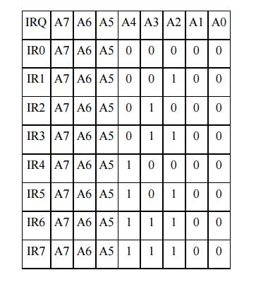
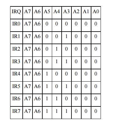
are provided if ADI=0. A4-A0 (or A5-A0) are set by 8259 itself:
ADI=1
(spacing 4 bytes)
ADI=0
(spacing 8 bytes)
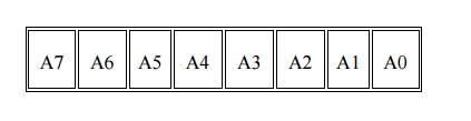
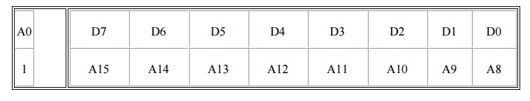
ICW2 (Initialization Command Word Two)
Higher
byte of ISR address (8085), or 8 bit vector address (8086).
ICW3 (Initialization Command Word Three)
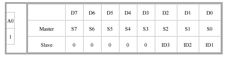
ü Master
mode: 1 indicates slave is present on that interrupt, 0 indicates direct
interrupt
ü Slave
mode: ID3-ID2-ID1 is the slave ID number. Slave 4 on IR4 has ICW3=04h (0000
0100)
ICW4 (Initialization Command Word Four)
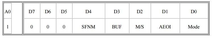
ü SFNM:
1=Special Fully Nested Mode, 0=FNM
ü M/S:
1=Master, 0=Slave
ü AEOI:
1=Auto End of Interrupt, 0=Normal
ü Mode:
0=8085, 1=8086
OCW1 (Operational Command Word One)
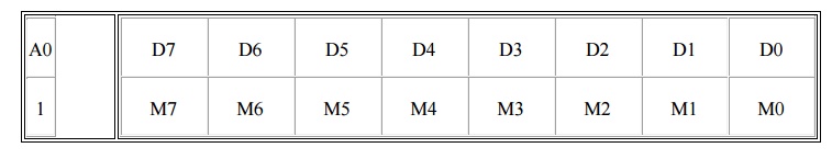
IRn is
masked by setting Mn to 1; mask cleared by setting Mn to 0 (n=0..7)
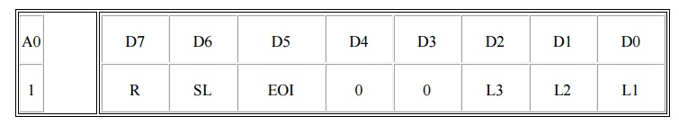
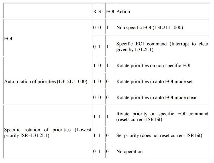
OCW2 (Operational Command Word Two)
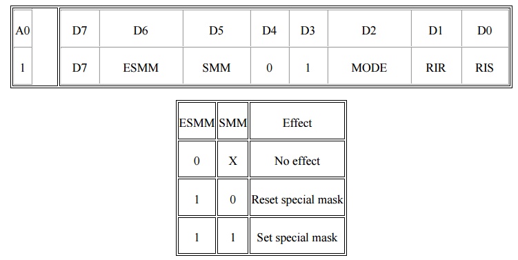
OCW3 (Operational Command Word Three)
Interrupt sequence (single PIC)
ü One or
more of the IR lines goes high.
ü Corresponding
IRR bit is set.
ü 8259
evaluates the request and sends INT to CPU.
ü CPU sends
INTA-bar.
ü Highest
priority ISR is set. IRR is reset.
ü 8259
releases CALL instruction on data bus.
ü CALL
causes CPU to initiate two more INTA-bar's.
ü 8259
releases the subroutine address, first lowbyte then highbyte.
ü ISR bit
is reset depending on mode.
Related Topics