Chapter: Mechanical : Computer Aided Design : Assembly of Parts
Production Drawing Limits, Fits and Tolerance
PRODUCTION DRAWING LIMITS, FITS AND TOLERANCE
Limit system
There are three terms used in the limit system:
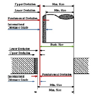
1. Tolerance: Deviation from a basic value is defined as Tolerance. It can be obtained by taking the difference between the maximum and minimum permissible limits.
2. Limits: Two extreme permissible sizes between which the actual size is contained are defined as limits.
3. Deviation: The algebraic difference between a size and its corresponding basic size. There are two types of deviations: 1) Upper deviation 2) Lower deviation
The fundamental deviation is eith er the upper or lower deviation, depending on which is closer to the basic size.
Tolerances
Due to human erro rs, machine settings, etc., it is nearly impossib le to manufacture an absolute dimension as specified by the designer. Deviation in dimensi ons from the basic value always arises. Thi s deviation of dimensions from the basic v alue is known as Tolerance.
The figure shows mechanical tolerances which occur during operations.
Fits
The relation between two mating parts is called fit. Depending upon the actual lim its of the hole or shaft sizes, fits may be classified as clearance fit, transition fit and interference fit.
Clearance fit
Clearance fit is defined as a cleara nce between mating parts. In clearance fit, ther e is always a positive clearance between the hole and shaft.
Transition fit
Transition fit may result in either an interference or clearance, depending upon th e actual values of the tolerance of individual parts.
Interference fit
Interference fit is obtained if the difference between the hole and shaft sizes is negative before assembly. Interference fit generally ranges from mini mum to maximum interference. The two extr eme cases of interference are as follows:
Minimum interference
The magnitude of the difference (negative) between the maximum size of the hole and the minimum size of the shaft in an interference fit before assembly.
Maximum interference
The magnitude of the difference between the minimum size of the hole and the maximum size of the shaft in an interference or a transition fit before assembly.
Hole Basis and shaft basis system:
In identifying limit dimensions for the three classes of fit, two systems are in use:
1. Hole basis system: The size of the shaft is obtained by subtracting the allowance from the basic size of the hole. Tolerances are then applied to each part separately. In this system, the lower deviation of the hole is zero. The letter symbol indication for this is 'H'.
2. Shaft basis system: The upper deviation of the shaft is zero, and the size of the hole is obtained by adding the allowance to the basic size of the shaft. The letter symbol indication is 'h'.
Related Topics