Chapter: Flexible Alternating Current Transmission System : Thyristor Controlled Series Capacitor (TCSC) and Applications
Modeling of TCSC(Thyristor Controlled Series Capacitor)
MODELING OF TCSC
A TCSC
involves continuous-time dynamics, relating to voltages and currents in the
capacitor and reactor, and nonlinear, discrete switching behavior of
thyristors. Deriving an appropriate model for such a controller is an intricate
task.
1. Variable-Reactance Model
1.1 Introduction
Ø A TCSC
model for transient- and oscillatory-stability studies, used widely for its
simplicity, is the variable-reactance model depicted in Fig.
Ø In this
quasi-static approximation model, the TCSC dynamics during power-swing
frequencies are modeled by a variable reactance at fundamental frequency.
Ø The other
dynamics of the TCSC model—the variation of the TCSC response with different
firing angles.
Ø It is
assumed that the transmission system operates in a sinusoidal steady state,
with the only dynamics associated with generators and PSS.
Ø This
assumption is valid, because the line dynamics are much faster than the
generator dynamics in the frequency range of 0.1–2 Hz that are associated with
angular stability studies.
Ø As
described previously, the reactance-capability curve of a single-module TCSC,
as depicted in Fig. exhibits a discontinuity between the inductive and
capacitive regions.
Ø However,
this gap is lessened by using a multimode TCSC. The variable-reactance TCSC
model assumes the availability of a continuous-reactance range and is therefore
applicable for multi module TCSC configurations.
Ø This
model is generally used for inter-area mode analysis, and it provides high
accuracy when the reactance-boost factor (=XTCSC/
XC) is less than 1.5.
2. Transient – Stability Model
Ø In the
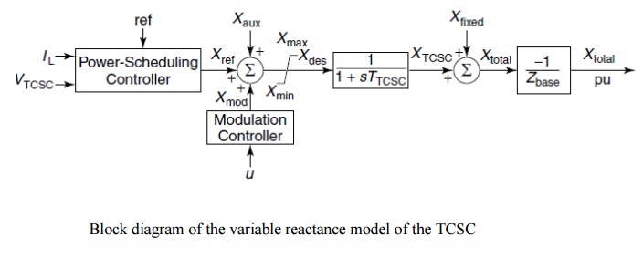
variable-reactance model for stability studies, a reference value of TCSC
reactance, Xref, is generated
from a power-scheduling controller based on the power-flow specification in the transmission line.
Ø The
reference Xref value may
also be set directly by manual control in response to an order from an
energy-control center, and it essentially represents the initial operating
point of the TCSC; it does not include the reactance of FCs (if any).
Ø The
reference value is modified by an additional input, Xmod, from a modulation controller for such purposes as
damping enhancement.
Ø Another
input signal, this applied at the summing junction, is the open-loop auxiliary
signal, Xaux, which can be
obtained from an external power-flow controller.
Ø A desired
magnitude of TCSC reactance, Xdes,
is obtained that is implemented after a finite delay caused by the firing controls
and the natural response of the TCSC. This delay is modeled by a lag circuit
having a time constant,TTCSC,
of typically 15–20 ms .
Ø The
output of the lag block is subject to variable limits based on the TCSC
reactance-capability curve shown in Fig.
Ø The
resulting XTCSC is added to the Xfixed, which is the
reactance of the TCSC installation’s FC component.
Ø To obtain
per-unit values, the TCSC reactance is divided by the TCSC base reactance, Zbase, given as
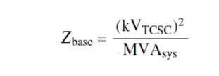
where ,
kVTCSC = the rms line–line voltage of the TCSC in kilovolts (kV)
MVAsys =
the 3-phase MVA base of the power system
Ø The TCSC
model assigns a positive value to the capacitive reactance, so Xtotal is multiplied by a
negative sign to ensure consistency with the convention used in load-flow and
stability studies.
Ø The TCSC
initial operating point, Xref,
for the stability studies is chosen as

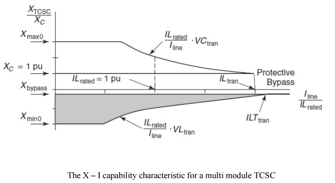
Ø The
reactance capability curve of the multimodal TCSC shown in Fig. can be simply
approximated by the capability curve shown in Fig.
Ø This
figure can be conveniently used for the variable-reactance model of TCSC, and
the capability curve that the figure depicts includes the effect of TCSC
transient overload levels.
Ø It should
be noted that the reactance limit for high currents is depicted in Fig. as a
group of discrete points for the different modules.
Ø During
periods of over current, only some TCSC modules move into the bypassed mode,
for the bypassing of a module causes the line current to decrease and thus
reduces the need for the remaining TCSC modules to go into the bypass mode.
Ø However,
for the case of modeling, only one continuous-reactance limit—denoted by a
vertical line in Fig is considered for all TCSC modules.
Ø All
reactance are expressed in per units on XC;
all voltages, in per units on ILrated.
XC and all currents, in
amps. In the capacitive region, the different TCSC reactance constraints are
caused by the following:
1. The limit on the TCSC firing angle, represented by constant reactance limit Xmax 0.
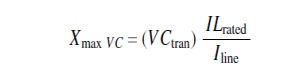
2. The limit
on the TCSC voltage VCtran.
The corresponding reactance constraint is give by
3.The limit on the line current (ILtran) beyond which the TCSC transpires
into the protective-bypass mode:
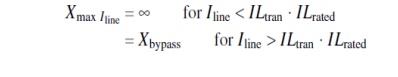
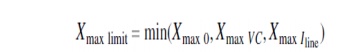
Ø The
effective capacitive-reactance limit is finally obtained as a minimum of the
following limits:
Ø In the
inductive region, the TCSC operation is restricted by the following limits:
o The limit on the firing angle, represented by
a constant-reactance limit Xmin 0.
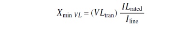
o
The harmonics-imposed limit, represented by a
constant-TCSC-voltage limit VLtran.
The equivalent-reactance constraint is given by
3. Long - Term – Stability Model
Ø The
capability curves of the TCSC depend on the duration for which the voltage- and
current-operating conditions persist on the TCSC.
Ø In
general, two time-limited regions of TCSC operation exist: the transient-overload region, lasting 3–10 s, and the
temporary-overload region, lasting 30 min; both are followed by the continuous
region. For long-term dynamic simulations, an overload-management function
needs to be incorporated in the control system.
Ø This
function keeps track of the TCSC variables and their duration of application,
and it also determines the appropriate TCSC overload range, for which it
modifies the Xmax limit
and Xmin limit. It then
applies the same modifications to the controller.
Ø The
variable-reactance model does not account for the inherent dependence of TCSC
response time on the operating conduction angle.
Ø Therefore,
entirely incorrect results may be obtained for the high-conduction-angle
operation of the TCSC or for whenever the power-swing frequency is high (>2
Hz) .
Ø However,
the model is used widely in commercial stability programs because of its
simplicity, and it is also used for system-planning studies as well as for
initial investigations of the effects of the TCSC in damping-power
oscillations.
Ø A reason
for the model’s widespread use lies in the assumption that controls designed to
compensate the TCSC response delay are always embedded in the control system by
the manufacturer and are therefore ideal.
Ø Hence the
response predicted by the model is a true replica of actual performance.
Ø In
situations where this assumption is not satisfied, a more detailed stability
model is required that accurately represents the inherent slow response of the
TCSC.
Related Topics