Chapter: Civil : Structural dynamics of earthquake engineering
Zero moment point method
Zero moment
point method
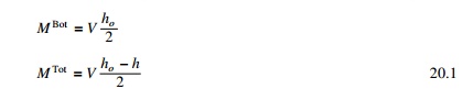
A one bay multi-storey framed building of height h and
width l is considered. Assume the building is subjected to lateral loads
as a result of ground motion. The bending moment diagram due to lateral loading
is shown in Fig. 20.1.
The position of the point where the moment is zero is defined
as the zero moment point (ZMP).
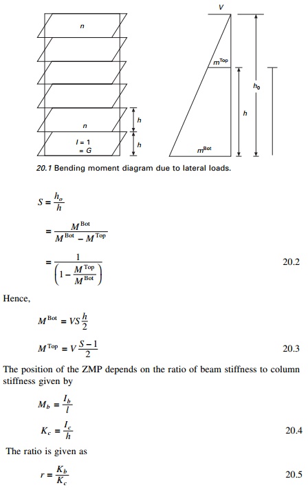
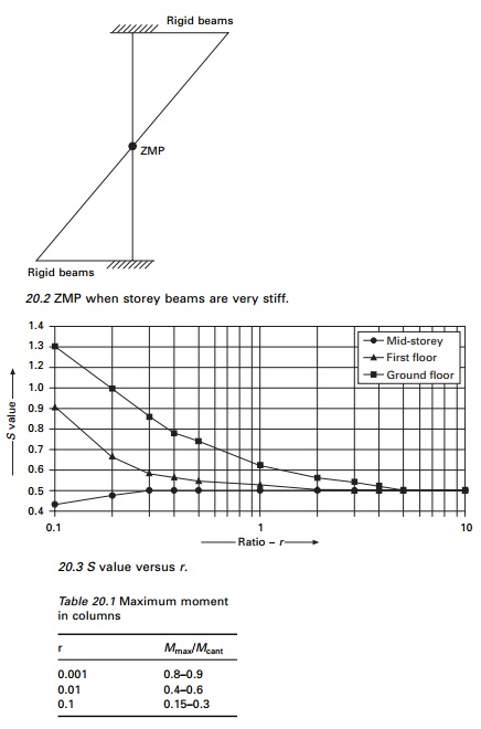
If storey beams are very stiff,
the ZMP lies at the mid-height of each storey and if the beams are very
flexible, the behaviour is more like a cantilever (see Fig. 20.2).
The approximate position of ZMP
will now be determined for uniform and non-uniform frames.
1 Uniform frames
It is assumed that storey heights
are constant and moments of inertia are constant at each storey. The frame is
analysed for inverted triangular load. Various analyses have been performed with
different values of beam to column stiffness as r = 0.01, 0.1, 0.5, 1,
2, 5, 10, 10 000. The positions of ZMP are as follows. The average values of S
is plotted for various values of r for ground storey, first floor and
mid-height of the building in Fig. 20.3.
• At first
storey S is 0.5–0.6 for r > 2 and greater than 1 for r
< 0.2 (ground).
• At
mid-heights S is about 0.5 for r > 0.5 average values of S
at ground floor, first floor and new mid-height floor are shown in Fig. 20.3.
It is to advisable to increase
the moments at mid-height by 10–20% with respect to moments based on Sm.
By relating maximum moment on columns
(Mmax) to that, acting on cantilever (Mcant)
the ratio of (Mmax/Mcant) as shown in Table
20.1 are obtained.
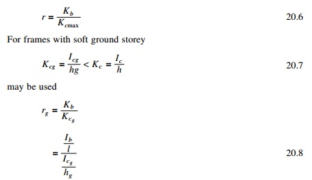
2 Non-uniform
frames
When the frame has a varying column moment of inertia but
constant beam moment of inertia, the frame can be analysed using the curves for
uniform moment of inertia as
3 Substitution in
equivalent frame method
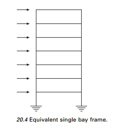
A multi-storey multi-bay frame is replaced by the equivalent
single bay frame shown in Fig. 20.4.
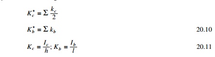
Studies show the deflection of the substitution frame is
identical to the actual frame. The bending moment in columns of the substitution
frame is
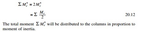
The distribution is accurate only if the beams are very stiff
(r > 10) or very flexible (r < 0.05). Hence computed
moments in interior columns have to be multiplied by the factors as
• for
ground floor – 1.1 to 1.2
• for other
floors – 1.2 to 1.3
Using equilibrium equations beam moment may be calculated.
4 Deflection
estimation
The deformed shape of one bay,
multi-storey structure depends on the ratio of stiffness of beam to column r
= kb/kc and on the type of loading 0.1 <
r < 5. The deformed shape is close to a straight line as advocated by
most seismic codes. The deflections are sensitive to changes in geometry and
rigidity and so only the order of magnitude can be estimated. When 2 < r
< 5. it is strong beam–weak column design and 0.01 < r < 1 is
the weak beam and strong column design which is preferred for earthquake
design.
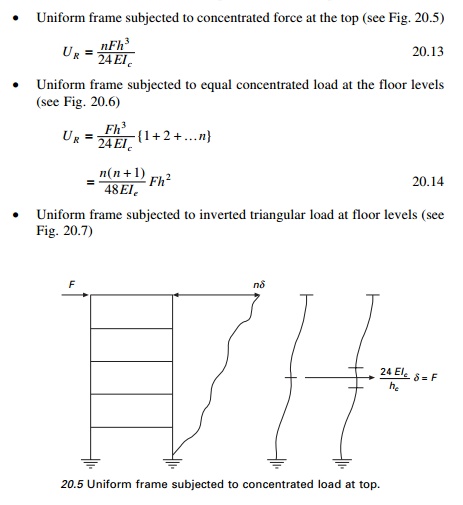
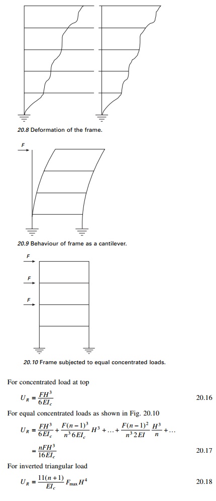
Uniform frame subjected to concentrated force at the top (see
Fig. 20.5)
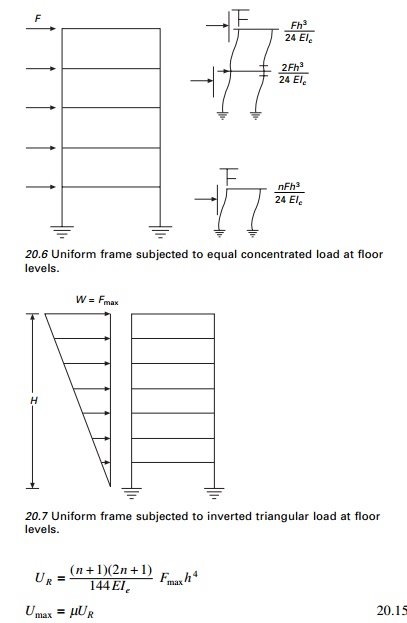
Uniform frame subjected to equal concentrated load at the
floor levels (see Fig. 20.6)
Uniform frame subjected to inverted triangular load at floor
levels (see Fig. 20.7)
The average value of µ is shown in Fig. 20.11 which may be used for any lateral load
distribution.
For high values of beam stiffness (weak columns and strong
beam) (r >> 1) the frame deforms as shown in Fig. 20.8. For low
values of beam stiffness (strong columns and weak beam) r < 0.1 the
frame behaves like of cantilever shown in Fig. 20.9.
The deflection calculations are required for checking storey
drafts.
For regular frames, since the deflection shape is a straight
line, the following relation holds good (see Fig. 20.11).
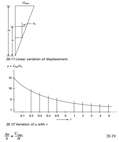
For buildings with the height of the ground floor (hg)
> height of floors above h is (hg > h)
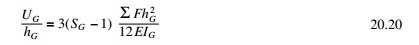
where SG
can be taken from graph (Fig. 20.3).
Related Topics