Chapter: Mobile Communication
Wireless Communication
Wireless Communication
Contents
:
1.
Cellular systems
2.
Frequency Management and Channel
Assignment
3.
Types of handoff and their
characteristics
4.
MAC
5.
SDMA
6.
FDMA
7.
TDMA
8.
CDMA
9.
Cellular Wireless Networks
Pre requisite Discussion :
In
this unit we discuss what is cellular systems and how the frequency and
channels are allocated. Medium access control tells how to reduce traffic in
the network and we discuss about frequency , time, space and code division
multiple access.
1. Cellular Systems:
Concept :
Cellular
telephone systems must accommodate a large number of users over a large
geographic area with limited frequency spectrum, i.e., with limited number of
channels. If a single transmitter/ receiver is used with only a single base
station, then sufficient amount of power may not be present at a huge distance
from the BS. For a large geographic coverage area, a high powered transmitter
therefore has to be used. But a high power radio transmitter causes harm to
environment. Mobile communication thus calls for replacing the high power
transmitters by low power transmitters by dividing the coverage area into small
segments, called cells. Each cell uses a certain number of the available
channels and a group of adjacent cells together use all the available channels.
Such a group is called a cluster. This cluster can repeat itself and hence the
same set of channels can be used again and again.
Each
cell has a low power transmitter with a coverage area equal to the area of the
cell. This technique of substituting a single high powered transmitter by
several low powered transmitters to support many users is the backbone of the
cellular concept.
Significance :
In order to know how mobile is made
this is necessary.
2. Frequency Management and Channel Assignment:
Concept:
Channel
Assignment Strategies
With the rapid increase in number of
mobile users, the mobile service providers had to follow strategies which
ensure the effective utilization of the limited radio spectrum. With increased
capacity and low interference being the prime objectives, a frequency reuse
scheme was helpful in achieving this objectives. A variety of channel
assignment strategies have been followed to aid these objectives. Channel
assignment strategies are classified into two types: fixed and dynamic.
Fixed
Channel Assignment (FCA)
In fixed channel assignment strategy
each cell is allocated a fixed number of voice channels. Any communication
within the cell can only be made with the designated unused channels of that particular
cell. Suppose if all the channels are occupied, then the call is blocked and
subscriber has to wait. This is simplest of the channel assignment strategies
as it requires very simple circuitry but provides worst channel utilization.
Later there was another approach in which the channels were borrowed from
adjacent cell if all of its own designated channels were occupied. This was
named as borrowing strategy. In such cases the MSC supervises the borrowing
process and ensures that none of the calls in progress are interrupted.
Dynamic
Channel Assignment (DCA)
In dynamic channel assignment
strategy channels are temporarily assigned for use in cells for the duration of
the call. Each time a call attempt is made from a cell the corresponding BS
requests a channel from MSC. The MSC then allocates a channel to the requesting
the BS. After the call is over the channel is returned and kept in a central
pool. To avoid co-channel interference any channel that in use in one cell can
only be reassigned simultaneously to another cell in the system if the distance
between the two cells is larger than minimum reuse distance. When compared to
the FCA, DCA has reduced the likelihood of blocking and even increased the
trunking capacity of the network as all of the channels are available to all
cells, i.e., good quality of service. But this type of assignment strategy
results in heavy load on switching center at heavy traffic condition.
Significance:
This is used to know how the
frequency is assigned to cells and how the channels are clustered in heavy and
less traffic conditions.
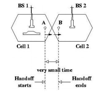
3. Handoff Process
Concept:
When a user moves from one cell to
the other, to keep the communication between the user pair, the user channel
has to be shifted from one BS to the other without interrupting the call, i.e.,
when a MS moves into another cell, while the conversation is still in progress,
the MSC automatically transfers the call to a new FDD channel without
disturbing the conversation. This process is called as handoff. Processing of
handoff_ is an important task in any cellular system. Handoffs must be
performed successfully and be imperceptible to the users. Once a signal level
is set as the minimum acceptable for good voice quality (Prmin), then a
slightly stronger level is chosen as the threshold (PrH)at which handoff has to
be made, as shown. A parameter, called power margin, defined as quite an
important parameter during the handoff process since this margin can neither be
too large nor too small. If is too small, then there may not be enough time to
complete the handoff and the call might be lost even if the user crosses the
cell boundary. If it is too high o the other hand, then MSC has to be burdened
with unnecessary handoffs. This is because MS may not intend to enter the other
cell. Therefore it should be judiciously chosen to ensure imperceptible
handoffs and to meet other objectives.
Significance:
Handoff
is used to know how the call is continued without any interrupt when the mobile
node moves from one base station to other.
4. MAC:
Concept:
MAC
is a data
communication protocol. It is a sub layer of the data link layer, which itself is layer 2. The MAC sub layer
provides addressing and channel access control mechanisms that make it possible
for several terminals or network nodes to communicate within a multiple access
network that incorporates a shared medium, e.g. Ethernet. It is also referred
to as a medium access controller.
CSMA
/CD
The Carrier Sense Multiple Access
(CSMA) with Collision Detection (CD) protocol is used to control access to the
shared Ethernet medium. A switched network (e.g. Fast Ethernet) may use a full
duplex mode giving access to the full link speed when used between directly
connected two NICs, Switch to NIC cables, or Switch to Switch cables.
Significance:
It is used for mobile nodes to
communicate without any infrastructure. Overcomes the Near and Far terminal and
Hidden-Exposed terminal problems
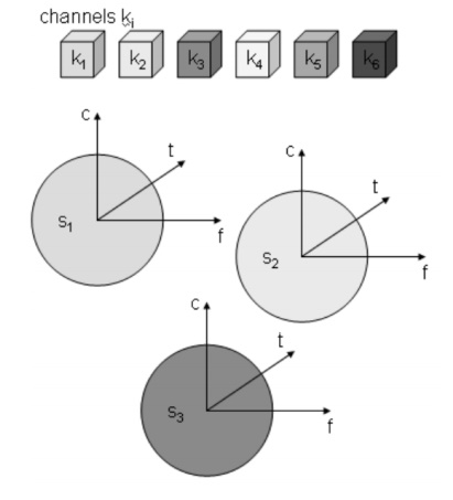
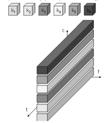
5. Space Division Multiplexing
Six channels ki introduces a three
dimensional coordinate system.
It shows the dimensions of code c,
time t and frequency t. Space division multiplexing (SDM) the (three
dimensional) space si is also shown. The channels k1 to k3 can be mapped onto
the three spaces s1 to s3 which clearly separate the channels and prevent the
interference ranges from overlapping. The space between the interference ranges
is sometimes called guard space. Such a guard space is needed in all 4
multiplexing schemes presented. The remaining channels(k4 to k6) three
additional spaces would be needed. In wireless transmission SDM implies a
separate sender for each communication channel with a wide enough distance
between senders.
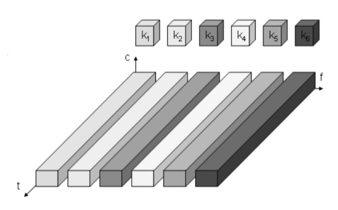
6. Frequency Division Multiplexing (FDM)
FDM schemes to subdivide the
frequency dimension into several non-overlapping frequency bands.Each channel
k1 is now allotted its frequency band as indicated. Senders using a certain
frequency band can use this band continuously. Guard spaces are needed to avoid
frequency band overlapping called adjacent channel interference.
This is used in radio stations
within the same region where each radio station has its own frequency.
Significance:
No
dynamic coordination necessary
Works
also or analog signals
Disadvantages
Waste
of bandwidth if the traffic is distributed unevenly
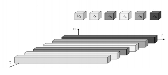
7. Time Division Multiplexing (TDM)
Here channels k1 is given the whole
bandwidth for a certain amount of time i.e all senders use the same frequency
but at different point of time Guard spaces which represent time gaps have to
separate the different periods when the senders use the medium. If two
transmissions overlap in time this is called co-interference. To avoid this
type of interference precise synchronization between different senders is
necessary.
Significance:
Only one carrier in the medium at
any time
Throughput high even for many users
Disadvantages
Precise
synchronization necessary
8. Code Division Multiplexing
Each channel has a unique code
All channels use the same spectrum at the same
time
Guard spaces are ralises by using codes with
the necessary distance in code space Ex.
Orthogonal codes
Implemented using spread spectrum technology
Significance:
Bandwidth
efficient
No
coordination and synchronization necessary
Good
protection against interference and tapping
Disadvantages
Varying
user data rates
More
complex signal regeneration
9. Cellular Wireless Network
The DSSS receiver is more complex than the transmitter.
The receiver only has to perform the inverse functions of the two transmitter
modulation steps. However, noise and multi-path propagation require additional
mechanisms to reconstruct the original data. The first step in the receiver
involves demodulating the received signal. This is achieved using the same
carrier as the transmitter reversing the modulation and results in a signal
with approximately the same bandwidth as the original spread spectrum signal.
Additional filtering can be applied to generate this signal. While demodulation
is well known from ordinary radio receivers, the next steps constitute a real
challenge for DSSS receivers, contributing to the complexity of the system. The
receiver has to know the original chipping sequence, i.e., the receiver
basically generates the same pseudo random sequence as the transmitter.
Sequences at the sender and receiver have to be precisely synchronized because
the receiver calculates the product of a chip with the incoming signal. This
comprises another XOR operation as explained in section 3.5, together with a
medium access mechanism that relies on this scheme. During a bit period, which
also has to be derived via synchronization, an integrator adds all these products. Calculating the
products of chips and signal, and adding the products in an integrator is also
called correlation, the device a correlator. Finally, in each bit period a
decision unit samples
the sums generated by the integrator and decides if this sum represents a binary 1 or a 0. If
transmitter and receiver are perfectly synchronized and the signal is not too
distorted by noise or multi-path propagation,. On the receiver side, this
signal is XORed bit-wise after
demodulation with the same Barker code as chipping sequence. This results in
the sum of products equal to 0 for the first bit and to 11 for the second bit.
The decision unit can now map the first sum (=0) to a binary 0, the second sum
(=11) to a binary 1 this constitutes the original user data. In real life,
however, the situation is somewhat more complex. Assume that the demodulated
signal shows some distortion, e.g., 1010010100001101000111.
Additionally, the different paths may have
different path losses. In this case, using so-called rake receivers provides a
possible solution. A rake receiver uses n correlators for the n strongest paths.
Each correlator is synchronized to the transmitter plus the delay on that
specific path. As soon as the receiver detects a new path which is stronger
than the currently weakest path, it assigns this new path to the correlator
with the weakest path. The output of the correlators are then combined and fed
into the decision unit. Rake receivers can even take advantage of the
multi-path propagation by combining the different paths in a constructive way
Significance:
Used real time in organizations and used in
smart phones. GPS in Taxies, Emergency alerts, etc
Application:
∑ Mobile Communication
∑ GPS systems
∑ Emergency System