Chapter: Electric Energy Generation and Utilisation and Conservation : Wind Energy
Wind Energy Conversion
Wind Energy Conversion
The fact that the wind is variable and intermittent source of energy is immaterial for some application such as pumbing water for land drainage-provided, of course, that there is a broad match between the energy supplied over any critical period and the energy required. If the wind blows, the job gets done; if it does not, the job waits.
However, for many of the uses to which electricity is put, the interruption of supply may be highly inconvenient. Operators or users of wind turbines must ensure that there is some from of back-up can take the form of
(1) Battery storage
(2) Connection with the local electricity distribution systems, or
(3) A stand by generator powered by liquid or gaseous fuels
For utility responsible for public supply, the integration of medium sized and large wind turbines into their distribution network could required some additional plant which is capable of responding quickly to meet fluctuating demand.
1. Small Producers
Private citizens in several countries have won to right to operate wind generator and other renewable energy systems and to export power to the grid. For most small wind generators this requires that the output is conditioned, so that in the frequency and phase of the mains supply. Only few small units are designed to maintain a constant rotational rate, so that can be synchronized to the mains frequency and feed electricity directly into the grid. Most current (DC) or variable output Alternating current (AC).
Power conditioning is readily achieved using an electronic black-box called a “Synchronous Inverter” and although this is an expensive item of equipment, it does eliminate the need for batteries and for conversion of home appliances to run on DC.
Where there is no grid connection, electricity that is surplus to immediately requirements must be stored on site using heavy duty batteries. It can be recovered later when the demand exceeds the supply. An alternative is to dump it (by generating and dissipating heat) or better, to convert it into heat that can be stored, for example as hot water in a well insulated tank.
2. Large Producers
Large and medium-sized wind generators are designed to give a stable and constant electrical output over a wide range of wind speeds and to feed current directly into the grid, they operate primarily as fuel savers, reducing the utility’s total fuel burn.
The choice of generator type depends on the size of the local distribution grid and its associated generating capacity.
An induction generator would normally be used where there is a significant amount of other generating capacity (which could provide the necessary reactive power for excitation). Induction generators are robust and reliable and require minimal control equipment.
For isolated networks where other local generating capacity is limited, a synchronous generator is more appropriate. Synchronous generator are more complex and therefore more expensive than induction machines.
3. Lift and Drag Force
The extraction of power, and hence energy, from the wind depends on creating certain forces and applying them to rotate (or to translate) a mechanism. There are two primary mechanisms for producing forces from the wind: Lift and Drag.
By definition of Lift forces act perpendicular to the air flow, while drag forces act in the direction flow.
Lift forces are produced by changing the velocity of the air stream flowing over either side of the lifting surface. Speeding up the air flow causes the pressure to drop, while slowing the air stream down leads to increase in pressure.
In other words, any change in velocity generates a pressure difference across the lifting surface. This pressure difference produces a force that begins to act on the high pressure side and moves towards the low pressure side of the lifting surface which is called an airfoil.
A Good airfoil has a high lit/drag ratio, in some cases it can generate lift forces perpendicular to the air stream direction that are 30 times as great as the drag force parallel to the flow. The lift increases as the angle formed at the junction of the airfoil and the air stream (the angle of attack) becomes less and less actute, upon the point where the angle of the airflow on the low pressure side becomes excessive. When this happens, the air flow breaks away from the low pressure side.
A lot of turbulence ensues, the lit decreases and the drag increases quite substantially; this phenomenon is known as Stalling.
For efficient operation, a wind turbine blade needs to function with as much lift and as little drag as possible because drag dissipates energy. As lift does not involves anything more complex than deflecting the air flow, it is usually an efficient process. The design of each wind turbine speciies the angle at which the airfoil should bet set to achieve the maximum lift to drag ratio.
In addition to airfoils, there are two other mechanisms for creating lift. One is the so-called Magnus Effect, caused by spinning a cylinder in an air stream at a high-speed of rotation. The spinnings slows down the air speed on the side where the cylinder is moving into wind and increases it on the other side; the result is similar to an airfoil. This principle has been put to practical use in one or two cases but is not generally employed. The second way is to blow air through narrow slots in a cylinder, so that it emerges tangentially; this is known as a Thwaits Slot.
Thwaits Slots also creates a rotation (or circulation) of airflow, which in turn generate lift. Because the lift drag ratio of airfoils is generally much better than those of rotating or slotted cylinders, the latter techniques probably have little practical potential.
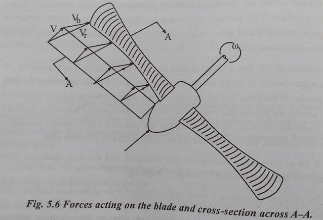
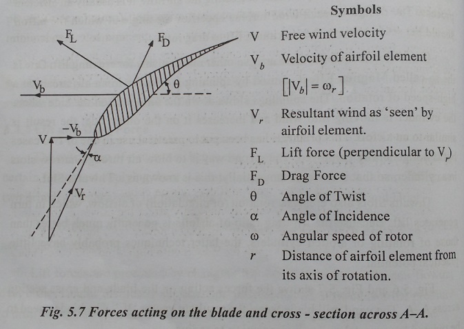
Fig. 5.6 and Fig. 5.7 shows the forces acting on the blade and cross section across A-A. The wind mill balde ‘sees’ the resultant vector ‘Vf’. The blades need to be twisted because ‘r’ varies in proportion to radius.
Related Topics