Chapter: Power System Operation and Control : Reactive Power -Voltage Control
Voltage Control Method
VOLTAGE CONTROL METHOD
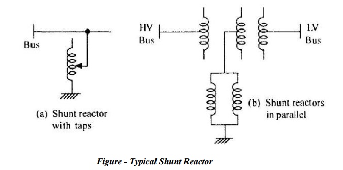
1. Reactors
Ø Inductive reactors absorb reactive power and may be used in circuits, series or shunt connected, while series connected reactors are used to limit fault currents, shunt reactors are used for var control.
Ø Reactors installed at line ends and intermediate substations can compensate up to 70% of charging power while the remaining 30% power at no-load can be provided by the under excited operation of the generator.
Ø With increase in load, generator excitation may be increased with reactors gradually cut-out.
Ø Figure shows some typical shunt reactor arrangements
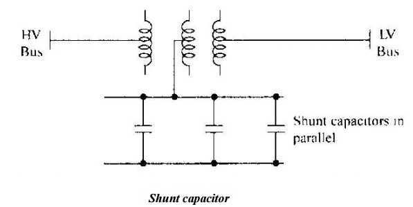
2. Shunt Capacitors
Ø Capacitors produce var and may be connected in series or shunt in the system.
Ø Series capacitors compensate the line reactance in long overhead lines and thus improve the stability limit.
Ø However, they give rise to additional problems like high voltage transients, sub-synchronous resonance, etc.
Ø Shunt capacitors are used for reactive compensation.
Ø Simplicity and low cost are the chief considerations for using shunt capacitor.
Ø Further, for expanding systems additions can be made.
Ø Fig. shows the connected of shunt capacitors through the tertiary of a transformer.
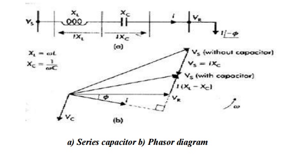
3. Series capacitors
Ø Here the capacitors are connected in series with the line.
Ø The main aim is to reduce the inductive reactance between supply point and the load.
Ø The major disadvantage of the method is, whenever short circuit current flows through the capacitor, protective devices like spark gaps and non linear resistors are to be in corporate.
Ø Phasor diagram for a line with series capacitor is shown in the figure (b).
4. Relative merits between shunt and series capacitors.
1. If the load var requirement is small, series capacitors are of little help.
2. If the voltage drop is the limiting factor, series capacitors are effective; also to some extent the voltage fluctuations can be evened.
3. If the total line reactance is high, series capacitors are very effective and stability is improved.
4. With series capacitors the reduction in line current is small, hence if the thermal considerations limits the current, little advantage is from this, so shunt compensation is to be used.
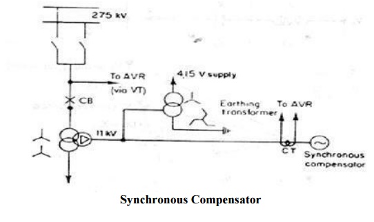
Synchronous compensators:
Ø A synchronous compensator is a synchronous motor running without a mechanical load and depending on the excitation level; it can either absorb or generate reactive power.
Ø When used with a voltage regulator the compensator can automatically run overexcited at times of high loads and under excited at light loads.
Ø A typical connection of a compensator is shown in the figure along with the associated voltage – var output characteristics
Ø A great advantage of the method is the flexible operation for all load conditions.
Ø Being a rotating machine, its stored energy is useful for riding through transient disturbances, including voltage drops.
Related Topics