Chapter: Distributed and Cloud Computing: From Parallel Processing to the Internet of Things : Virtual Machines and Virtualization of Clusters and Data Centers
Virtual Clusters and Resource Management
VIRTUAL CLUSTERS AND RESOURCE MANAGEMENT
A physical cluster is a collection of servers (physical machines)
interconnected by a physical network such as a LAN. In Chapter 2, we studied
various clustering techniques on physical machines. Here, we introduce virtual
clusters and study its properties as well as explore their potential
applications. In this section, we will study three critical design issues of
virtual clusters: live
migration of VMs, memory
and file migrations, and dynamic
deployment of virtual clusters.
When a
traditional VM is initialized, the administrator needs to manually write
configuration information or specify the configuration sources. When more VMs
join a network, an inefficient configuration always causes problems with
overloading or underutilization. Amazon’s Elastic Compute Cloud (EC2) is a good example of a web
service that provides elastic computing power in a cloud. EC2 permits customers to create VMs
and to manage user accounts over the time of their use. Most virtualization
platforms, including XenServer and VMware ESX Server, support a brid-ging mode
which allows all domains to appear on the network as individual hosts. By using
this mode, VMs can communicate with one another freely through the virtual
network interface card and configure the network automatically.
1. Physical versus Virtual Clusters
Virtual clusters are built
with VMs installed at distributed servers from one or more physical clus-ters.
The VMs in a virtual cluster are interconnected logically by a virtual network
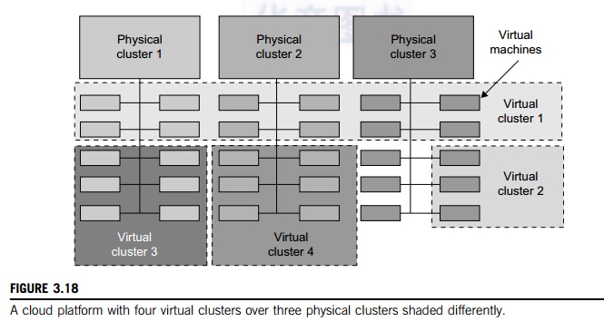
across several physical networks. Figure 3.18 illustrates the concepts of
virtual clusters and physical clusters. Each virtual cluster is formed with
physical machines or a VM hosted by multiple physical clusters. The virtual
cluster boundaries are shown as distinct boundaries.
The
provisioning of VMs to a virtual cluster is done dynamically to have the
following interest-ing properties:
• The virtual cluster nodes can
be either physical or virtual machines. Multiple VMs running with different
OSes can be deployed on the same physical node.
• A VM runs with a guest OS,
which is often different from the host OS, that manages the resources in the
physical machine, where the VM is implemented.
• The purpose of using VMs is
to consolidate multiple functionalities on the same server. This will greatly
enhance server utilization and application flexibility.
• VMs can be colonized
(replicated) in multiple servers for the purpose of promoting distributed parallelism,
fault tolerance, and disaster recovery.
• The size (number of nodes) of
a virtual cluster can grow or shrink dynamically, similar to the way an overlay
network varies in size in a peer-to-peer (P2P) network.
• The failure of any physical
nodes may disable some VMs installed on the failing nodes. But the failure of
VMs will not pull down the host system.
Since
system virtualization has been widely used, it is necessary to effectively
manage VMs running on a mass of physical computing nodes (also called virtual
clusters) and consequently build a high-performance virtualized computing
environment. This involves virtual cluster deployment, monitoring and
management over large-scale clusters, as well as resource scheduling, load
balancing, server consolidation, fault tolerance, and other techniques. The
different node colors in Figure 3.18 refer to different virtual clusters. In a
virtual cluster system, it is quite important to store the large number of VM
images efficiently.
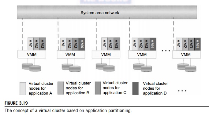
Figure
3.19 shows the concept of a virtual cluster based on application partitioning
or customi-zation. The different colors in the figure represent the nodes in
different virtual clusters. As a large number of VM images might be present,
the most important thing is to determine how to store those images in the
system efficiently. There are common installations for most users or
applica-tions, such as operating systems or user-level programming libraries.
These software packages can be preinstalled as templates (called template VMs).
With these templates, users can build their own software stacks. New OS
instances can be copied from the template VM. User-specific components such as
programming libraries and applications can be installed to those instances.
Three
physical clusters are shown on the left side of Figure 3.18. Four virtual
clusters are created on the right, over the physical clusters. The physical
machines are also called host
systems. In contrast, the VMs are guest systems. The host and guest systems may run with different
operating
systems. Each VM can be
installed on a remote server or replicated on multiple servers belonging to the
same or different physical clusters. The boundary of a virtual cluster can
change as VM nodes are added, removed, or migrated dynamically over time.
1.1
Fast Deployment and Effective Scheduling
The system should have the
capability of fast deployment. Here, deployment means two things: to construct
and distribute software stacks (OS, libraries, applications) to a physical node
inside clus-ters as fast as possible, and to quickly switch runtime
environments from one user’s virtual cluster to another
user’s virtual cluster. If one
user finishes using his system, the corresponding virtual cluster should shut
down or suspend quickly to save the resources to run other VMs for other users.
The
concept of “green computing” has attracted much attention recently.
However, previous approaches have focused on saving the energy cost of
components in a single workstation without a global vision. Consequently, they
do not necessarily reduce the power consumption of the whole clus-ter. Other
cluster-wide energy-efficient techniques can only be applied to homogeneous
workstations and specific applications. The live migration of VMs allows
workloads of one node to transfer to another node. However, it does not
guarantee that VMs can randomly migrate among themselves. In fact, the
potential overhead caused by live migrations of VMs cannot be ignored.
The
overhead may have serious negative effects on cluster utilization, throughput,
and QoS issues. Therefore, the challenge is to determine how to design
migration strategies to implement green computing without influencing the
performance of clusters. Another advantage of virtualiza-tion is load balancing
of applications in a virtual cluster. Load balancing can be achieved using the
load index and frequency of user logins. The automatic scale-up and scale-down
mechanism of a virtual cluster can be implemented based on this model. Consequently,
we can increase the resource utilization of nodes and shorten the response time
of systems. Mapping VMs onto the most appro-priate physical node should promote
performance. Dynamically adjusting loads among nodes by live migration of VMs
is desired, when the loads on cluster nodes become quite unbalanced.
1.2
High-Performance Virtual Storage
The template VM can be
distributed to several physical hosts in the cluster to customize the VMs. In
addition, existing software packages reduce the time for customization as well
as switching virtual environments. It is important to efficiently manage the
disk spaces occupied by template software packages. Some storage architecture
design can be applied to reduce duplicated blocks in a distributed file system
of virtual clusters. Hash values are used to compare the contents of data
blocks. Users have their own profiles which store the identification of the
data blocks for corresponding VMs in a user-specific virtual cluster. New
blocks are created when users modify the corresponding data. Newly created
blocks are identified in the users’ profiles.
Basically, there are four steps to deploy a
group of VMs onto a target cluster: preparing
the disk image, configuring the VMs,
choosing the destination nodes, and executing the VM deployment command on every host. Many systems use templates to
simplify the disk image preparation process. A template is a disk image that
includes a preinstalled operating system with or without certain application
software. Users choose a proper template according to their requirements and
make a duplicate of it as their own disk image. Templates could implement the COW (Copy on Write) format. A new COW backup file is very small
and easy to create and transfer. Therefore, it definitely reduces disk space
consumption. In addition, VM deployment time is much shorter than that of
copying the whole raw image file.
Every VM
is configured with a name, disk image, network setting, and allocated CPU and
memory. One needs to record each VM configuration into a file. However, this
method is inefficient when managing a large group of VMs. VMs with the same
configurations could use preedited profiles to simplify the process. In this
scenario, the system configures the VMs according to the chosen pro-file. Most
configuration items use the same settings, while some of them, such as UUID, VM
name, and IP address, are assigned with automatically calculated values.
Normally, users do not care which host is running their VM. A strategy to
choose the proper destination host for any VM is needed. The deployment
principle is to fulfill the VM requirement and to balance workloads among the
whole host network.
2. Live VM Migration Steps and
Performance Effects
In a cluster built with mixed
nodes of host and guest systems, the normal method of operation is to run
everything on the physical machine. When a VM fails, its role could be replaced
by another VM on a different node, as long as they both run with the same guest
OS. In other words, a physical node can fail over to a VM on another host. This
is different from physical-to-physical failover in a tradi-tional physical
cluster. The advantage is enhanced failover flexibility. The potential drawback
is that a VM must stop playing its role if its residing host node fails.
However, this problem can be mitigated with VM life migration. Figure 3.20
shows the process of life migration of a VM from host A to host B. The
migration copies the VM state file from the storage area to the host machine.
There are four ways to manage a virtual
cluster. First, you can use a guest-based manager, by which the cluster manager resides on a
guest system. In this case, multiple VMs form a virtual cluster. For example,
openMosix is an open source Linux cluster running different guest systems on
top of the Xen hypervisor. Another example is Sun’s cluster Oasis, an experimental Solaris
cluster of VMs supported by a VMware VMM. Second, you can build a cluster
manager on the host systems. The host-based manager supervises the guest systems and can restart
the guest system on another physical machine. A good example is the VMware HA system that can
restart a guest system after failure.
These two cluster management systems are either
guest-only or host-only, but they do not mix. A third way to manage a virtual
cluster is to use an independent cluster manager on both the host and guest systems. This will
make infrastructure management more complex, however. Finally, you can use an integrated cluster on the guest and host systems. This means the
manager must be designed to distinguish between virtualized resources and
physical resources. Various cluster management schemes can be greatly enhanced
when VM life migration is enabled with minimal overhead.
VMs can be live-migrated from one physical
machine to another; in case of failure, one VM can be replaced by another VM.
Virtual clusters can be applied in computational grids, cloud platforms, and
high-performance computing (HPC) systems. The major attraction of this scenario
is that virtual cluster-ing provides dynamic resources that can be quickly put
together upon user demand or after a node failure. In particular, virtual
clustering plays a key role in cloud computing. When a VM runs a live ser-vice,
it is necessary to make a trade-off to ensure that the migration occurs in a
manner that minimizes all three metrics. The motivation is to design a live VM
migration scheme with negligible downtime, the lowest network bandwidth
consumption possible, and a reasonable total migration time.
Furthermore, we should ensure that the
migration will not disrupt other active services residing in the same host
through resource contention (e.g., CPU, network bandwidth). A VM can be in one
of the following four states. An inactive
state is defined by the virtualization platform,
under which
the VM is not enabled. An active state refers to a VM that has been instantiated at
the virtualization platform to perform a real task. A paused state corresponds to a VM that has been instantiated
but disabled to process a task or paused in a waiting state. A VM enters the suspended state if its machine file and virtual resources are
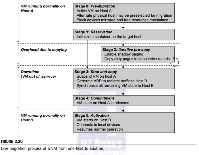
stored back to the disk. As shown in Figure 3.20, live migration of a VM
consists of the following six steps:
Steps 0
and 1: Start migration. This step makes preparations for the migration,
including determining the migrating VM and the destination host. Although users
could manually make a VM migrate to an appointed host, in most circumstances,
the migration is automatically started by strategies such as load balancing and
server consolidation.
Steps 2: Transfer memory.
Since the whole execution state of the VM is stored in memory, sending the VM’s memory to the destination node ensures
continuity of the service provided by the VM. All of the memory data is
transferred in the first round, and then the migration controller recopies the
memory data which is changed in the last round. These steps keep iterating
until the dirty portion of the memory is small enough to handle the final copy.
Although precopying memory is performed iteratively, the execution of programs
is not obviously interrupted.
Step 3:
Suspend the VM and copy the last portion of the data. The migrating VM’s execution is suspended when the last round’s memory data is transferred. Other nonmemory
data such as CPU and network states should be sent as well. During this step,
the VM is stopped and its applications will no longer run. This “service unavailable” time is called the “downtime” of migration, which should be as short as
possible so that it can be negligible to users.
Steps 4
and 5: Commit and activate the new host. After all the needed data is copied,
on the destination host, the VM reloads the states and recovers the execution
of programs in it, and the service provided by this VM continues. Then the
network connection is redirected to the new VM and the dependency to the source
host is cleared. The whole migration process finishes by removing the original
VM from the source host.
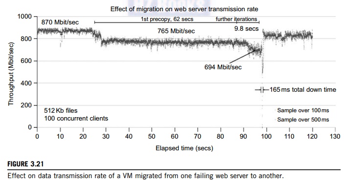
Figure
3.21 shows the effect on the data transmission rate (Mbit/second) of live
migration of a VM from one host to another. Before copying the VM with 512 KB
files for 100 clients, the data throughput was 870 MB/second. The first precopy
takes 63 seconds, during which the rate is reduced to 765 MB/second. Then the
data rate reduces to 694 MB/second in 9.8 seconds for more iterations of the
copying process. The system experiences only 165 ms of downtime, before the VM
is restored at the destination host. This experimental result shows a very
small migration overhead in live transfer of a VM between host nodes. This is
critical to achieve dynamic cluster reconfiguration and disaster recovery as
needed in cloud computing. We will study these techniques in more detail in Chapter
4.
With the emergence of
widespread cluster computing more than a decade ago, many cluster
con-figuration and management systems have been developed to achieve a range of
goals. These goals naturally influence individual approaches to cluster management.
VM technology has become a popular method for simplifying management and
sharing of physical computing resources. Platforms
such as VMware and Xen allow
multiple VMs with different operating systems and configurations to coexist on
the same physical host in mutual isolation. Clustering inexpensive computers is
an effective way to obtain reliable, scalable computing power for network
services and compute-intensive applications
3. Migration of Memory, Files, and
Network Resources
Since clusters have a high
initial cost of ownership, including space, power conditioning, and cool-ing
equipment, leasing or sharing access to a common cluster is an attractive
solution when demands vary over time. Shared clusters offer economies of scale
and more effective utilization of resources by multiplexing. Early
configuration and management systems focus on expressive and scalable
mechanisms for defining clusters for specific types of service, and physically
partition cluster nodes among those types. When one system migrates to another
physical node, we should consider the following issues.
3.1
Memory Migration
This is one of the most
important aspects of VM migration. Moving the memory instance of a VM from one
physical host to another can be approached in any number of ways. But
traditionally, the concepts behind the techniques tend to share common
implementation paradigms. The techniques employed for this purpose depend upon
the characteristics of application/workloads supported by the guest OS.
Memory
migration can be in a range of hundreds of megabytes to a few gigabytes in a
typical system today, and it needs to be done in an efficient manner. The Internet Suspend-Resume (ISR) technique exploits temporal
locality as memory states are likely to have considerable overlap in the
suspended and the resumed instances of a VM. Temporal locality refers to the
fact that the memory states differ only by the amount of work done since a VM
was last suspended before being initiated for migration.
To
exploit temporal locality, each file in the file system is represented as a
tree of small subfiles. A copy of this tree exists in both the suspended and
resumed VM instances. The advantage of using a tree-based representation of
files is that the caching ensures the transmission of only those files which
have been changed. The ISR technique deals with situations where the migration
of live machines is not a necessity. Predictably, the downtime (the period
during which the service is unavailable due to there being no currently
executing instance of a VM) is high, compared to some of the other techniques
discussed later.
3.2
File System Migration
To support VM migration, a
system must provide each VM with a consistent, location-independent view of the
file system that is available on all hosts. A simple way to achieve this is to
provide each VM with its own virtual disk which the file system is mapped to
and transport the contents of this virtual disk along with the other states of
the VM. However, due to the current trend of high-capacity disks, migration of
the contents of an entire disk over a network is not a viable solution. Another
way is to have a global file system across all machines where a VM could be
located. This way removes the need to copy files from one machine to another
because all files are network-accessible.
A
distributed file system is used in ISR serving as a transport mechanism for
propagating a suspended VM state. The actual file systems themselves are not
mapped onto the distributed file system. Instead, the VMM only accesses its
local file system. The relevant VM files are explicitly copied into the local
file system for a resume operation and taken out of the local file system for a
suspend operation. This approach relieves developers from the complexities of
implementing several different file system calls for different distributed file
systems. It also essentially disassociates the VMM from any particular
distributed file system semantics. However, this decoupling means that the VMM
has to store the contents of each VM’s virtual disks in its local files, which have
to be moved around with the other state information of that VM.
In smart copying, the VMM exploits spatial
locality. Typically, people often move between the same small number of
locations, such as their home and office. In these conditions, it is possible
to transmit only the difference between the two file systems at suspending and
resuming locations. This technique significantly reduces the amount of actual
physical data that has to be moved. In situations where there is no locality to
exploit, a different approach is to synthesize much of the state at the
resum-ing site. On many systems, user files only form a small fraction of the
actual data on disk. Operating system and application software account for the
majority of storage space. The proactive state transfer solution works in those
cases where the resuming site can be predicted with reasonable confidence.
3.3
Network Migration
A migrating VM should maintain
all open network connections without relying on forwarding mechanisms on the
original host or on support from mobility or redirection mechanisms. To enable
remote systems to locate and communicate with a VM, each VM must be assigned a
virtual IP address known to other entities. This address can be distinct from
the IP address of the host machine where the VM is currently located. Each VM
can also have its own distinct virtual MAC address. The VMM maintains a mapping
of the virtual IP and MAC addresses to their corresponding VMs. In general, a
migrating VM includes all the protocol states and carries its IP address with
it.
If the
source and destination machines of a VM migration are typically connected to a
single switched LAN, an unsolicited ARP reply from the migrating host is
provided advertising that the IP has moved to a new location. This solves the
open network connection problem by reconfiguring all the peers to send future
packets to a new location. Although a few packets that have already been transmitted
might be lost, there are no other problems with this mechanism. Alternatively,
on a switched network, the migrating OS can keep its original Ethernet MAC
address and rely on the network switch to detect its move to a new port.
Live migration means moving a VM from one
physical node to another while keeping its OS environment and applications
unbroken. This capability is being increasingly utilized in today’s enter-prise environments to provide efficient online system
maintenance, reconfiguration, load balancing, and proactive fault tolerance. It
provides desirable features to satisfy requirements for computing resources in
modern computing systems, including server consolidation, performance
isolation, and ease of management. As a result, many implementations are
available which support the feature using disparate functionalities.
Traditional migration suspends VMs before the transportation and then resumes
them at the end of the process. By importing the precopy mechanism, a VM could
be live-migrated without stopping the VM and keep the applications running
during the migration.
Live migration is a key feature of system
virtualization technologies. Here, we focus on VM migration within a
cluster environment where a network-accessible storage system, such as storage area network (SAN) or network attached storage (NAS), is employed. Only
memory and CPU status needs to be transferred from
the source node to the target node. Live migration techniques mainly use the
precopy approach, which first transfers all memory pages, and then only copies
modified pages during the last round iteratively. The VM service downtime is
expected to be minimal by using iterative copy operations. When applications’ writable working set becomes small, the VM is
suspended and only the CPU state and dirty pages in the last round are sent out
to the destination.
In the precopy phase, although a VM service is
still available, much performance degradation will occur because the migration
daemon continually consumes network bandwidth to transfer dirty pages in each
round. An adaptive rate limiting approach is employed to mitigate this issue,
but total migration time is prolonged by nearly 10 times. Moreover, the maximum
number of iterations must be set because not all applications’ dirty pages are ensured to converge to a small writable working
set over multiple rounds.
In fact, these issues with the precopy approach are caused by the large
amount of transferred data during the whole migration process. A
checkpointing/recovery and trace/replay approach (CR/ TR-Motion) is proposed to
provide fast VM migration. This approach transfers the execution trace file in
iterations rather than dirty pages, which is logged by a trace daemon.
Apparently, the total size of all log files is much less than that of dirty
pages. So, total migration time and downtime of migration are drastically
reduced. However, CR/TR-Motion is valid only when the log replay rate is larger
than the log growth rate. The inequality between source and target nodes limits
the application scope of live migration in clusters.
Another strategy of postcopy is introduced for
live migration of VMs. Here, all memory pages are transferred only once during
the whole migration process and the baseline total migration time is reduced.
But the downtime is much higher than that of precopy due to the latency of
fetching pages from the source node before the VM can be resumed on the target.
With the advent of multicore or many-core machines, abundant CPU resources are
available. Even if several VMs reside on a same mul-ticore machine, CPU
resources are still rich because physical CPUs are frequently amenable to
multi-plexing. We can exploit these copious CPU resources to compress page
frames and the amount of transferred data can be significantly reduced. Memory
compression algorithms typically have little memory overhead. Decompression is
simple and very fast and requires no memory for decompression.
3.4
Live Migration of VM Using Xen
In Section 3.2.1, we studied Xen as a VMM or hypervisor,
which allows multiple commodity OSes to share x86 hardware in a safe and
orderly fashion. The following example explains how to perform live migration
of a VM between two Xen-enabled host machines. Domain 0 (or Dom0) performs
tasks to create, terminate, or migrate to another host. Xen uses a send/recv
model to transfer states across VMs.
Example 3.8 Live Migration of VMs between Two
Xen-Enabled Hosts
Xen supports live migration. It is a useful
feature and natural extension to virtualization platforms that allows for the
transfer of a VM from one physical machine to another with little or no
downtime of the services hosted by the VM. Live migration transfers the working
state and memory of a VM across a net-work when it is running. Xen also supports
VM migration by using a mechanism called Remote Direct
Memory
Access (RDMA).
RDMA speeds up VM migration by avoiding TCP/IP
stack processing overhead. RDMA implements a different transfer protocol whose
origin and destination VM buffers must be registered before any transfer
operations
occur, reducing it to a “one-sided” interface. Data communication over RDMA
does not need to involve the CPU, caches, or context switches. This allows
migration to be carried out with minimal impact on guest operating systems and
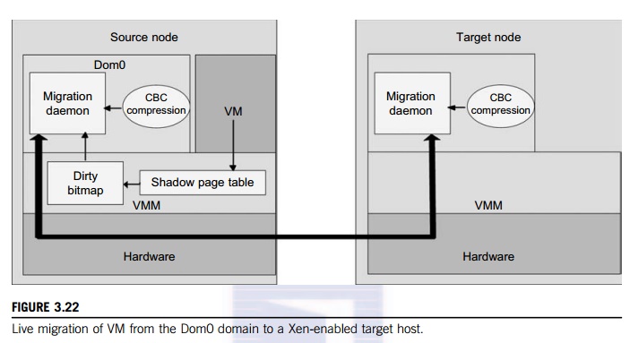
hosted applications. Figure 3.22 shows the a compression scheme for VM
migration.
This
design requires that we make trade-offs between two factors. If an algorithm
embodies expecta-tions about the kinds of regularities in the memory footprint,
it must be very fast and effective. A single compression algorithm for all
memory data is difficult to achieve the win-win status that we expect.
Therefore, it is necessary to provide compression algorithms to pages with
different kinds of regularities. The structure of this live migration system is
presented in Dom0.
Migration
daemons running in the management VMs are responsible for performing migration.
Shadow page tables in the VMM layer trace modifications to the memory page in
migrated VMs during the precopy phase. Corresponding flags are set in a dirty
bitmap. At the start of each precopy round, the bitmap is sent to the migration
daemon. Then, the bitmap is cleared and the shadow page tables are destroyed
and re-created in the next round. The system resides in Xen’s management VM.
Memory pages denoted by bitmap are extracted and compressed before they are
sent to the destination. The compressed data is then decompressed on the
target.
4. Dynamic Deployment of Virtual Clusters
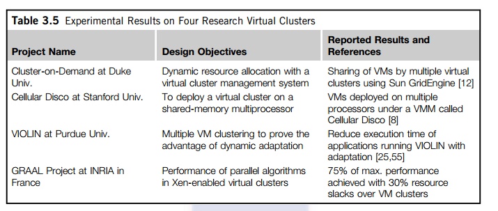
Table 3.5 summarizes four
virtual cluster research projects. We briefly introduce them here just to
identify their design objectives and reported results. The Cellular Disco at
Stanford is a virtual cluster built in a shared-memory multiprocessor system.
The INRIA virtual cluster was built to test parallel algorithm performance. The
COD and VIOLIN clusters are studied in forthcoming examples.
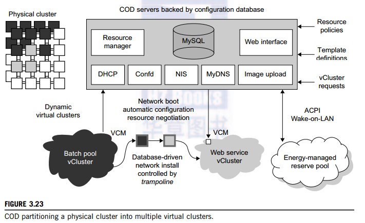
Example 3.9 The Cluster-on-Demand (COD) Project
at Duke University
Developed by researchers at Duke University,
the COD (Cluster-on-Demand) project is a virtual cluster management system for
dynamic allocation of servers from a computing pool to multiple virtual
clusters [12]. The idea is illustrated by the prototype implementation of the
COD shown in Figure 3.23. The COD
partitions
a physical cluster into multiple virtual clusters (vClusters). vCluster owners
specify the operating systems and software for their clusters through an
XML-RPC interface. The vClusters run a batch schedule from Sun’s GridEngine on
a web server cluster. The COD system can respond to load changes in
restruc-turing the virtual clusters dynamically.
The Duke researchers used the
Sun GridEngine scheduler to demonstrate that dynamic virtual clusters are an
enabling abstraction for advanced resource management in computing utilities
such as grids. The system supports dynamic, policy-based cluster sharing
between local users and hosted grid services. Attractive features include
resource reservation, adaptive provisioning, scavenging of idle resources, and
dynamic instantiation of grid services. The COD servers are backed by a
configuration database. This system provides resource policies and template
definition in response to user requests.
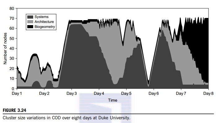
Figure 3.24 shows the variation in the number
of nodes in each of three virtual clusters during eight days of a live
deployment. Three application workloads requested by three user groups are
labeled “Systems,” “Architecture,” and “BioGeometry” in the trace plot. The experiments
were performed with multiple SGE batch pools on a test bed of 80 rack-mounted
IBM xSeries-335 servers within the Duke clus-ter. This trace plot clearly shows
the sharp variation in cluster size (number of nodes) over the eight days.
Dynamic provisioning and deprovisioning of virtual clusters are needed in
real-life cluster applications.
Example 3.10 The VIOLIN Project at Purdue
University
The
Purdue VIOLIN Project applies live VM migration to reconfigure a virtual
cluster environment. Its purpose is to achieve better resource utilization in
executing multiple cluster jobs on multiple cluster domains. The project
leverages the maturity of VM migration and environment adaptation technology.
The approach is to enable mutually isolated virtual environments for executing
parallel applications on top of a shared physical infrastructure consisting of
multiple domains. Figure 3.25 illustrates the idea with five concurrent virtual
environments, labeled as VIOLIN 1–5, sharing two physical clusters.
The
squares of various shadings represent the VMs deployed in the physical server
nodes. The major contribution by the Purdue group is to achieve autonomic
adaptation of the virtual computation environments as active, integrated
entities. A virtual execution environment is able to relocate itself across the
infrastructure, and can scale its share of infrastructural resources. The
adaptation is transparent to both users of virtual environments and
administrations of infrastructures. The adaptation overhead is maintained at 20
sec out of 1,200 sec in solving a large NEMO3D problem of 1 million particles.
The message being conveyed here is that the
virtual environment adaptation can enhance resource utilization significantly
at the expense of less than 1 percent of an increase in total execution time.
The
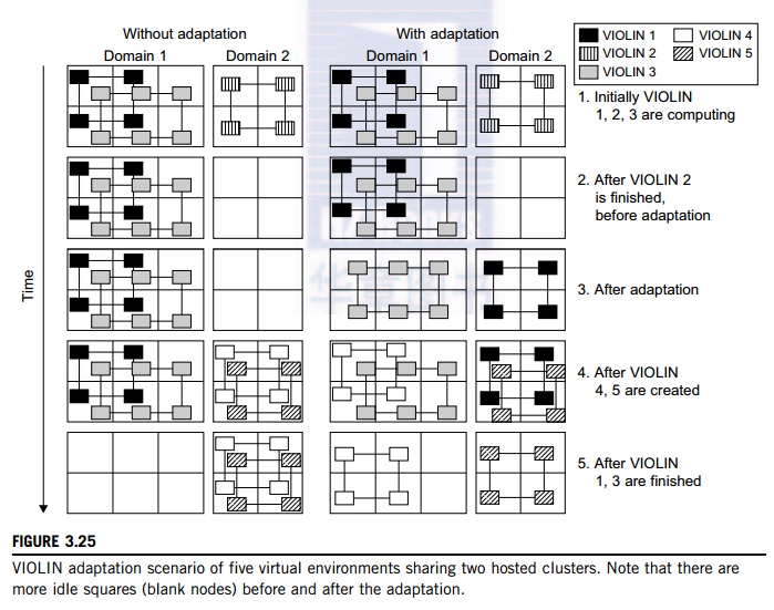
migration
of VIOLIN environments does pay off. Of course, the gain in shared resource
utilization will bene-fit many users, and the performance gain varies with
different adaptation scenarios. We leave readers to trace the execution of
another scenario in Problem 3.17 at the end of this chapter to tell the
differences. Virtual networking is a fundamental component of the VIOLIN
system.
Related Topics