Chapter: Computer Networks : Data Link Layer
Virtual-Circuit Networks: Frame Relay and ATM
Virtual-Circuit Networks: Frame
Relay and ATM
Two
common WAN technologies use virtual-circuit switching. Frame Relay is a
relatively high-speed protocol that can provide some services not available in
other WAN technologies such as DSL, cable TV, and T lines. ATM, as a high-speed
protocol, can be the superhighway of communication when it deploys physical
layer carriers such as SONET.
Frame Relay:
Frame
Relay is a virtual-circuit wide-area network that was designed in response to
demands for a new type of WAN.
1. Prior
to Frame Relay, some organizations were using a virtual-circuit switching
network called X.25 that performed switching at the network layer.
Drawbacks of X.25:
1.
X.25 has a low 64-kbps data rate. There was a need
for higher data-rate WANs.
2.
X.25 has extensive flow and error control at both
the data link layer and the network layer.
3.
Originally X.25 was designed for private use, not
for the Internet.
4.
Disappointed with X.25, some organizations started
their own private WAN by leasing T-l or T-3 lines from public service
providers.
Drawbacks:
a)
If an organization has n branches spread over an area, it needs n(n - 1)/2 T-1 or T-3 lines. The organization pays for all these
lines although it may use the lines only 10 percent of the time. This can be
very costly:
b) The
services provided by T-I and T-3 lines assume that the user has fixed-rate data
all the time. For example, a T-l line is designed for a user who wants to use
the line at a consistent 1.544 Mbps. This type of service is not suitable for
the many users today that need to send bursty data.
In
response to the above drawbacks, Frame Relay was designed.
Features:
a) Frame
Relay operates at a higher speed (1.544 Mbps and recently 44.376 Mbps). This
means that it can easily be used instead of a mesh of T-I or T-3 lines.
b)Frame
Relay operates in just the physical and data link layers. This means it can
easily be used as a backbone network to provide services to protocols that
already have a network layer protocol, such as the Internet.
c) Frame
Relay allows bursty data.
d) Frame
Relay allows a frame size of 9000 bytes, which can accommodate all local area
network frame sizes.
e) Frame
Relay is less expensive than other traditional WANs.
f) Frame
Relay has error detection at the data link layer only. There is no flow control
or error control.
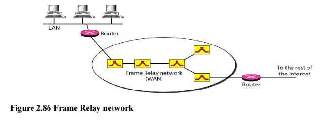
1. Architecture
Frame
Relay provides permanent virtual circuits and switched virtual circuits. The
routers are used, to connect LANs and WANs in the Internet. In the figure, the
Frame Relay WAN is used as one link in the global Internet.
Virtual Circuits
Frame
Relay is a virtual circuit network. A virtual circuit in Frame Relay is
identified by a number called a data link connection identifier (DLCI). VCIs in Frame Relay are called
DLCIs.
Switches
Each
switch in a Frame Relay network has a table to route frames. The table matches
an incoming port-DLCI combination with an outgoing port-DLCI combination. The
only difference is that VCIs are replaced by DLCIs.
2. Frame Relay Layers
Frame
Relay has only physical and data link layers.
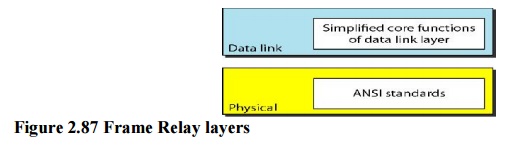
Physical
Layer
No
specific protocol is defined for the physical layer in Frame Relay. Instead, it
is left to the implementer to use whatever is available. Frame Relay supports
any of the protocols recognized by ANSI.
Data Link
Layer
At the
data link layer, Frame Relay uses a simple protocol that does not support flow
or error control. It only has an error detection mechanism. The address field
defines the DLCI as well as some bits used to control congestion.
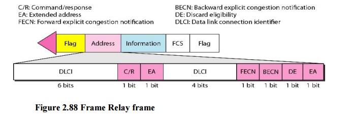
The
descriptions of the fields are as follows:
·
Address
(DLCI) field. The first 6 bits of the first byte makes up the
first part of theDLCI. The second part of the DLCI uses the first 4 bits of the
second byte. These bits are part of the l0-bit data link connection identifier
defined by the standard.
·
Command/response
(CIR). The command/response (C/R) bit is provided to allow upperlayers to
identify a frame as either a command or a response. It is not used by the Frame
Relay protocol.
·
Extended
address (EA). The extended address (EA) bit indicates whether the
currentbyte is the final byte of the address. An EA of 0 means that another
address byte is to follow. An EA of 1 means that the current byte is the final
one.
·
Forward
explicit congestion notification (FECN). The forward explicit
congestionnotification (FECN) bit can be set by any switch to indicate that
traffic is congested. This bit informs the destination that congestion has
occurred.
·
Backward
explicit congestion notification (BECN). The backward explicit
congestionnotification (BECN) bit is set to indicate a congestion problem in
the network. This bit informs the sender that congestion has occurred.
·
Discard
eligibility (DE). The discard eligibility (DE) bit indicates the
priority level ofthe frame. In emergency situations, switches may have to
discard frames to relieve bottlenecks and keep the network from collapsing due
to overload.
Related Topics