Chapter: Solid State Drives : Induction Motor Drives
Vector Control of AC Induction Machines
Vector Control of AC Induction Machines
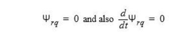
Vector control is the most popular control technique of AC induction motors. In special reference frames, the expression for the electromagnetic torque of the smooth-air-gap machine is similar to the expression for the torque of the separately excited DC machine. In the case of induction machines, the control is usually performed in the reference frame (d-q) attached to the rotor flux space vector. That’s why the implementation of vector control requires information on the modulus and the space angle (position) of the rotor flux space vector. The stator currents of the induction machine are separated into flux- and torque-producing components by utilizing transformation to the d-q coordinate system, whose direct axis (d) is aligned with the rotor flux space vector. That means that the q-axis component of the rotor flux space vector is always zero:
The rotor flux space vector calculation and transformation to the d-q coordinate system require the high computational power of a microcontroller. The digital signal processor is suitable for this task. The following sections describe the space vector transformations and the rotor flux space vector calculation.
Block Diagram of the Vector Control
Shows the basic structure of the vector control of the AC induction motor. To perform vector control, it is necessary to follow these steps:
• Measure the motor quantities (phase voltages and currents)
• Transform them to the 2-phase system (α,β) using a Clarke transformation
• Calculate the rotor flux space vector magnitude and position angle
• Transform stator currents to the d-q coordinate system using a Park transformation
• The stator current torque and flux producing components are separately controlled
• The output stator voltage space vector is calculated using the decoupling block
• The stator voltage space vector is transformed by an inverse Park transformation back from the d-q coordinate system to the 2-phase system fixed with the stator
• Using the space vector modulation, the output 3-phase voltage is generated
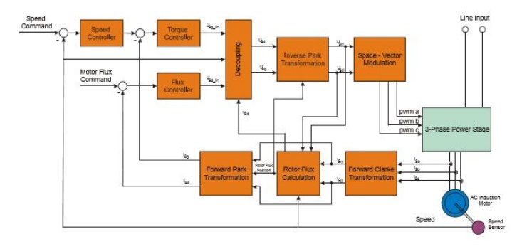
Block Diagram of the AC Induction Motor Vector Control
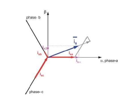
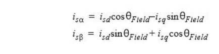
Forward and Inverse Clarke Transformation (a,b,c to α,β and backwards)
The forward Clarke transformation converts a 3-phase system a,b,c to a 2-phase coordinate system α,β. Figure shows graphical construction of the space vector and projection of the space vector to the quadrature-phase components α,β.
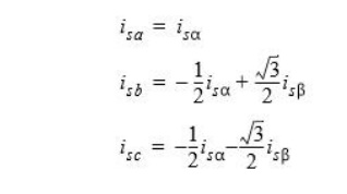
The inverse Clarke transformation goes back from a 2-phase (α,β) to a 3-phase isa, isb, isc system. For constant k=2/3, it is given by the following equations:
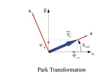
Forward and Inverse Park Transformation (α,β to d-q and backwards)
The components isα and isβ, calculated with a Clarke transformation, are attached to the stator reference frame α, β. In vector control, it is necessary to have all quantities expressed in the same reference frame. The stator reference frame is not suitable for the control process. The space vector isβ is rotating at a rate equal to the angular frequency of the phase currents. The components isα and isβ depend on time and speed. We can transform these components from the stator reference frame to the d-q reference frame rotating at the same speed as the angular frequency of the phase currents. Then the isd and isq components do not depend on time and speed. If we consider the d-axis aligned with the rotor flux, the transformation is illustrated in Figure where θfield is the rotor flux position.
The inverse Park transformation from the d-q to α,β coordinate system is given by the following equations:
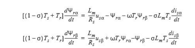
Rotor Flux Model
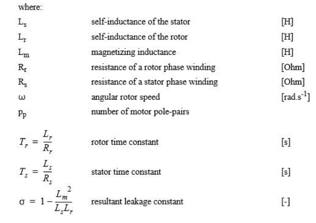
Knowledge of the rotor flux space vector magnitude and position is key information for the AC induction motor vector control. With the rotor magnetic flux space vector, the rotational coordinate system (d-q) can be established. There are several methods for obtaining the rotor magnetic flux space vector. The implemented flux model utilizes monitored rotor speed and stator voltages and currents. It is calculated in the stationary reference frame (α,β) attached to the stator. The error in the calculated value of the rotor flux, influenced by the changes in temperature, is negligible for this rotor flux model.
The rotor flux space vector is obtained by solving the differential equations (EQ 4-2) and (EQ 4-3), which are resolved into the α and β components. The equations are derived from the equations of the AC induction motor model
Related Topics