Chapter: Flexible Alternating Current Transmission System : Introduction
Uncompensated Transmission Lines
UNCOMPENSATED TRANSMISSION LINES
1. Introduction
For
simplicity let us consider only the inductive reactance
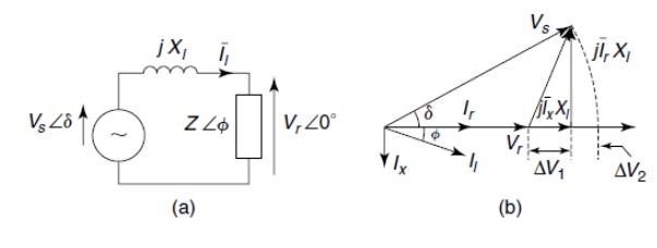
From the
above figure it is clear that between he sending and the receiving end voltages
and magnitude variation as well as a phase difference is created and the most
significant part of the voltage drop in the line reactance is due to the
reactive component of the load current and to keep the voltages in the network
nearly at the rated value.
Two compensation
methods are:
1. Load
compensation
2. System
compensation
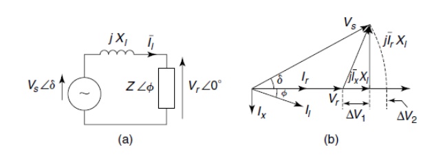
2. Load Compensation
Ø It is
possible to compensate for the reactive current of the load by adding a
parallel capacitive load so that Ic = Ix and the
effective power factor to become unity.
Ø In the
figure the absence of Ix eliminates the voltage drop ∆V1
bringing Vr closer in magnitude to Vs, this condition is
called load compensation and actually by charging extra for supplying the
reactive power a power utility company makes it advantageous for customers to
use load compensation on their premises.
Ø Loads
compensated to the unity power factor reduce the line drop but do not eliminate
it. They still experience a drop of ∆V2 from j IrX1.
3. System compensation
Ø To
regulate the receiving-end voltage at the rated value a power utility may
install a reactive-power compensator as shown in the figure and this
compensator draws a reactive current to overcome both components of the voltage
drop ∆V1 and ∆V2 as a consequence of the load current I1
through the line reactance X1.
Ø To
compensate for ∆V2 an additional capacitive current ∆Ic
over and above Ic that compensates for Ix is drawn by the
compensator.
Ø When ∆Ic
X1 = ∆V2 the receiving end voltage Vr equals
the sending end voltage Vs and such compensators are employed by
power utilities to ensure the quality of supply to their customers.
4. Lossless Distributed Parameter
Lines
Ø Most
power transmission lines are characterized by distributed parameters: Series
Resistance, Series Inductance, Shunt Conductance and Shunt Capacitance all
per-unit length and these parameters all depend on the conductor size, spacing,
and clearance above the ground, frequency and temperature of operation.
Ø In
addition these parameters depend on the bundling arrangement of the line
conductors and the nearness to other parallel lines.
5. Symmetrical Lines
Ø When the
voltage magnitudes at the two ends of a line are equal that is
Vs
= Vr =V and the line is said to be symmetrical because power
networks operate as voltage sources attempts are made to hold almost all node
voltages at nearly rated values. Therefore a symmetrical line presents a
realistic situation.
Ø Active
and Reactive powers of a transmission line are frequently normalized by
choosing the Surge-Impedance Load (SIL) as the base.
6. Midpoint Conditions of a
Symmetrical Line
Ø The
magnitude of the midpoint voltage depends on the power transfer and this
voltage influences the line insulation.
Ø For a
symmetrical line where the end voltages are held at nominal values the midpoint
voltage shows the highest magnitude variation.
Related Topics