Chapter: Aquaculture Engineering : Disinfection
Ultraviolet light - Disinfection in Aquaculture Engineering
Ultraviolet light
Function
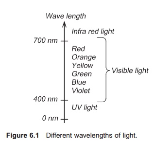
Ultraviolet (UV) light is electromagnetic radiation with a wavelength of 1ŌĆō400 nanometer (1 nm = 10ŌłÆ9 m) located at the lower end of the visible spectrum and beyond (Fig. 6.1) (the spectrum of visible light extends down to 380 nm). At the opposite end of the visible spectrum is the infrared (IR) region, heat radiation with longer wavelength which cannot be detected by the human eye.
The ability of the UV light to inactivate and destroy micro-organisms varies with both wave-length and the micro-organisms to be inactivated.
The most effective wavelength for general disinfec-tion is 250ŌĆō270 nm.4 UV light created by mercury vapour lamps will have a wavelength of 253.7 nm, which is effective for disinfection
Mode of action
UV light will damage the genetic material (DNA and/or RNA) in the micro-organism by disruption of the chains which results in inactivation and death. Inactivation (D) is proportional to the dose of radiation per unit area (intensity) of the UV light (I) and the exposure time (t):
D = It
The radiation dose is normally given in units of ╬╝Ws/cm2(microwatt second per centimetresquared), i.e. radiation intensity (energy) per unit area.
The effectiveness of the UV light depends on a number of factors including lamp intensity, age of the lamp, cleanliness of the lamp surface, distance between the lamp and the organism to be inacti-vated, type of organism to be inactivated, duration of UV exposure and purity of the water.
UV lamps become less efficient with use, and need to be replaced regularly, normally at least once a year. Normally the lamp is changed when its output has diminished to 60% of the original.5The intensity of the lamp should be measured to ensure sufficient exposure to UV radiation.
How well UV light passes through water depends on the characteristics of the water. UV transmission depends on the particle content (turbidity) of the water, for example. Transmission will be lower for re-used water than for new good quality inlet water. When dimensioning UV systems, it is therefore important to be aware of this.
Design
UV lamps can be placed either in the water (Fig. 6.2a,b) or above the water surface6 (Fig. 6.2c,d). Usually the lamps are placed in a chamber through which the water flows. UV chambers may be equipped with reflectors or turbulence discs to irra-diate the total water flow more effectively. The UV lamp is normally placed inside a quartz glass pipe to protect it from direct cooling by the water and fouling of the lamp surface.
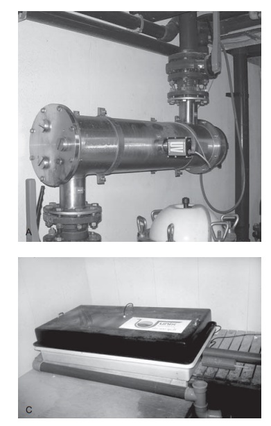
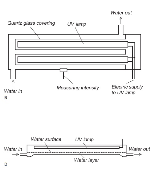
Figure 6.2 A UV plant can be constructed with UV lamps placed in the water flow, which is the usual arrangement (A, B), or above the water flow (C, D).
Fouling may occur on the quartz glass pipes which therefore must be cleaned regularly, either manually or automatically by washing with brushes, to maintain optimal UV intensity. Fouling will decrease UV transmission.
The intensity of the UV radiation can be mea-sured continuously and readings linked to a regulator, so that sufficient radiation intensity can be maintained in water of varying turbidity and with various extents of fouling on the pipes. If the radi-ation intensity decreases to a limiting value, an alarm can be activated so that remedial measures can be taken.
If the UV lamps are placed above the water surface, the water flows in a thin layer directly below them. In this system the UV rays must pass through the water surface and therefore must be more intense than in a submerged system. For the same reason, the layer of water is thin. As the lamps are above the water surface, fouling will not be so critical for this kind of system, but the problem of varying water quality will be the same as in plants where the UV lamp is placed inside the water flow.
Design specification
When designing the UV plant, the radiation dose, water retention time in the chamber, and the UV transmission must be specified. The transmission is given as the percentage of the known transmis-sion for distilled water. If the water is contaminated with particles, humus, etc. and is coloured, the transmission will decrease and must therefore be measured. This is normally performed for one dis-tance, for instance 5 cm. The transmission for other distances may then be found from the following equation:7
TL= T0L/L0
where:
TL=transmission through L cm of water
T0=transmission through L0cm of water
L =thickness of the water layer (cm)
L0=thickness of the water layer set at 1 cm.
Example
The UV transmission for re-used water of a given quality is found to be 90% through a 1 cm thick layer (i.e. 90% of the UV radiation passes through a water
layer 1 cm thick). Find the UV transmission for a 5 cm thick water layer.
Using the equation
TL = T0L/L0
where:
L =5 cm L0=1 cm
T0=90%=0.90
TL=0.905/1
= 0.59
Thus 59% of the initial UV radiation passes through a 5 cm thick water layer, i.e. the UV transmission is 59%.
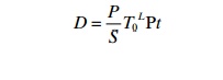
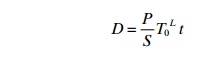
The UV intensity can be defined as the amount of radiation per unit surface area and the following equation can be used to find the radiation dose at distance L from the UV radiation source7:
where:
D =radiation dose (mWs/cm2) P =radiation effect (W)
S = area of radiated surface (cm2)
T0=the transmission of the water through 1 cm (%)
= thickness of the water layer that is radiated (cm)
t=necessary time for radiation (s).
Example
A UV tube is mounted in the middle of a cylindrical chamber of radius 5 cm. The length of the UV lamp is 1 m and therefore the largest radiated area will be 0.31 m2. The UV transmission through a 1 cm layer of water is 95%. The time from when the water enters the chamber to when it goes out is 10 s, so it is exposed to UV radition for 10 s. The UV radiation effect of the tube is 16 W.
Find the lowest UV radiation dose to which the water is exposed (this is close to the interior walls of the chamber, almost 5 cm from the UV tube).
Using the equation
where:
P = 16 W
S = 0.31 m2= 3100 cm2
T0= 95%
L = 5 cm
t = 10 s
D=0.0400 Ws/cm2
=40 mWs/cm2
To obtain good disinfection it is necessary to have a low content of particles and humus in the water, so these must be removed before the water enters the UV chamber, otherwise they will shield the micro-organisms from the UV radiation.
Dose
The dose required to kill pathogenic micro-organisms depends on the organism. In commercial plants a normal UV dose is in the range 30ŌĆō35 mWs/cm2, and this is adequate for a log disinfection of 3 of most of the common aquaculture bacte-ria.5,6,8,9 However, some viruses, such as IPN, are much more difficult to inactivate and doses of 100ŌĆō200 mWs/cm2 have been suggested.10 Care should be taken when reading papers where the effective dose rates are given, as the methods used in the laboratory are often different from those used in commercial aquaculture where, for instance, UV transmission through the water is variable.
Special problems
As previously described, particles can be a problem because they shade the micro-organisms from the UV light, so it is absolutely necessary to remove them before UV irradiation. If the water is very turbid, as may occur in systems with a high degree of water re-use, UV transmission may be so reduced that it is impossible to use a UV lamp for disinfection.
Related Topics