Chapter: Aquaculture Engineering : Feeding Systems
Types of feeding equipment
Types of feeding equipment
Feeding equipment can be divided into groups based on its construction and function. One classification is as follows:
· Feed blowers
· Feed dispenser
· Demand feeders
· Automatic feeders, feed machines
· Feeding systems.
This is specifically for the dry feed that is most commonly used in intensive fish farming. For wet and moist feed other separations can be made, but only a few methods are used for this type of feed. Feeding equipment for wet and moist feed will not be dealt with here.
Feed blowers
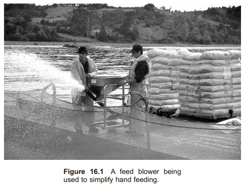
A feed blower is only a tool to simplify hand feeding (Fig. 16.1). There are different blower types based on the ‘carrier’ used for the feed particles which is normally either air or water. The feed can either be sucked up from a tank or a bag by vacuum, or the feed can be filled into a hopper standing over a pipe with flow of air or water. The hopper can be fixed on a boat or be movable.
Feed dispensers
A feed dispenser is often confused with a feeding machine, but does not have the distribution unit. Actually it is therefore something between a feed machine and hand feeding. A weighed portion of feed is placed on the dispenser and the dispenser will empty it during a fixed period, normally from one to three days. It either goes continuously or stepwise controlled by a control unit. To get the wanted feed ration, the actual amount of feed must be put in the dispenser. This is normally weighed out.
A great advantage with the feed dispenser is its simple and robust construction. It is also easy to monitor visually whenever it is functioning and the amount of feed that has been dispensed. The construction is favourable to use in research operations because if you weigh out the feed exactly you can be sure that the dispenser will supply the exact amount to the fish. The great disadvantage, com-pared to a feeding machine, is that it takes quite a long time to measure and/or weigh the feed that should be placed in the dispenser.
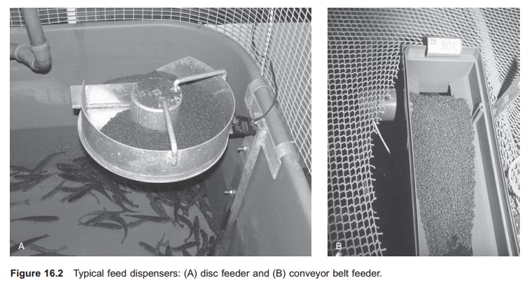
Several designs of feed dispenser are used (Fig. 16.2). In a disc feeder a scraper rotates on a horizontally fixed circular plate, and the feed falls off the edge of the plate and into the fish tank. A disc dispenser needs electricity to run the motor, normally 24 V a.c. The feeder normally goes step-wise, controled by a unit that regulates the start and stop intervals. Another much used construction is a rubber conveyor belt that is dragged along on rollers. When starting, the belt is dragged back-wards so it creates a surface where feed is supplied. The end of the belt is fixed to rollers; when these rotate the belt will be dragged up and the surface where the feed is lying will gradually be decreased so that the feed falls off and into the fish tank. This type is either powered by electricity or by clockwork. An advantage with this type of feed dispenser is the possibility of running it without electricity. Feed is either dispensed continuously or stepwise.
Demand feeders
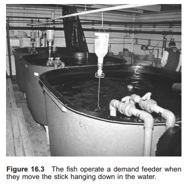
A demand feeder is normally a mechanical construction. A stick is attached to a slightly bowed plate sitting under a feed hopper (Fig. 16.3). The stick goes from the feeder down into the water. When the fish touch the stick, feed will be dispensed from the hopper. At the end of the stick is a knob, or something similar, which the fish touch. A great advantage with using demand feeders is that there is no need for an electricity supply. Furthermore, the design is simple with few moveable parts.
The fish operate the demand feeder themselves, and can therefore theoretically be fed according to appetite (ad libitum). However, some feed loss has been registered. The fish may use the demand stick as a toy and feed may be lost; demand feeders are also sensitive to movements in the water, such as waves; wind may also affect the demand feeder so shielding may be included.
Demand feeders are used for almost all species, even if some species, such as Atlantic salmon, are slow to learn the system. The fish need a training period to learn how to operate the system. Com-pared to hand feeding, both improved and less good growth results have been shown.
In electronic demand feeders feeding is triggered by electric signals. The mechanical stick is replaced by an electric cable with a pressure sensor at the end. When the fish touch this sensor a signal is given to the feeder which starts. This system allows extra control over the demand feeding, for instance by setting fixed interval for the operation of the feeder or by setting a maximum limit of distributed feed per portion or per day. A more advanced control system is, however, required in this type of feeder.
Much literature is available on the use of demand feeders, including the possibility for controlling the appetite of the fish experimentally.
Automatic feeders
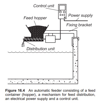
A feeding machine or an automatic feeder consists of four major components (Fig. 16.4): a feed container (hopper), a mechanism for feed distribution, an electrical power supply for the distribution mechanism and a control unit for starting and stopping the distribution mechanism. The feed distribu-tion mechanism is the main component in an automatic feeder and distinguishes it from a feed dispenser. The feeders are fixed in a rack on the tank or on the cage, but may also be included in a buoy (see, for example, ref. 13). When using an automatic feeder, the amount of feed that has to be distributed over a period of time is known and the distribution unit runs for the period that satisfies this requirement.
Feed is distributed by volume. In specially designed and more expensive feeders, the systems may also use feed mass. When using volume for distribution, the volume: mass ratio (litre/kg), i.e. the density, of the feed must be known. The density of the feed varies with formulation, from producer to producer, and also depends on the size of the feed particles. Because volume distribution feeders only distribute a certain volume of feed, and the in mass feed is of interest, calibration of the feeders is necessary. To calibrate the feeder, it is run for a known time period; then the exact amount of feed that has been dispensed is weighed so that the feed distributed per unit time can be calculated. This information is then used to find the necessary time that the feeder has to run to distribute a certain mass of feed.
Example
A fish tank requires 3 kg feed per day. For how long must the feeder be run to deliver this amount? First the amount of feed delivered from the feeder per unit time must be found. The feeder is run continuously for 1 min and the amount of feed delivered is weighed and found to be 1 kg. The feeder is there-fore delivering 1 kg/min; to deliver 3 kg to the fish tank, the feeder must be run for a total of 3 min per day.
If the feeder starts every 30 min throughout the day and night, it starts 48 times in total. Each time it must therefore run for: 3 min (= 180 s)/48 = 3.75 s.
Distribution mechanisms
Many mechanisms for feed distribution are avail-able. Some important types are described below.
Screw: A screw allows a specific batch of feed to bedispensed for every rotation (Fig. 16.5). The screw is installed under a hopper from which it is filled. The amount dispensed per unit time is related to screw diameter, design of the screw (rise of the screw thread), the speed of rotation, the degree of filling and the angle of the screw.
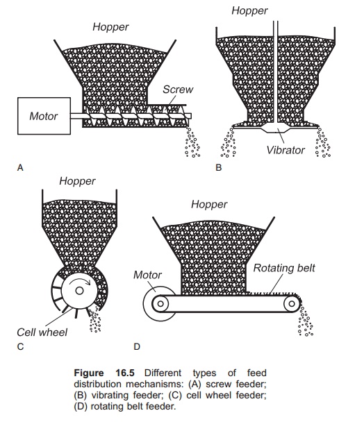
Vibrator: A plate that vibrates may be used to distribute a volume of feed. When the almost horizontally fixed plate starts to vibrate the feed on the plate will fall over the edge. One method of getting vibration is to attach a weight to one side of a vertically fixed shaft that rotates. When the shaft rotates there will be imbalance in the shaft and in the plate fixed to it. Another method is to use an electromagnet with an anchor fixed by a leaf or coil spring. When the electricity is turned on, the anchor is dragged towards the magnet by a varying magnetic field, making the whole vibrator shake; a slope on the feeding plate causes the feed to be shaken over the edge. Advantages of the electromagnetic vibrator are its simple construction and that it stops immediately the electricity is turned off. The amount of feed distributed is controlled by adjust-ing the voltage and hence the amplitude of the vibrator.
Cell wheel: A vertically installed rotating wheel with wings, cells or chambers sitting under a feed hopper may also be used to distribute feed (Fig. 16.5). When the wheel rotates it transports the feed in the cells; when the cells approach the lowest position, the feed is released. The amount of feed released depends on the number of chambers in the wheel and the speed of rotation. The leaf dispenser and drawer dispenser are similar in principle to the cell wheel.
Others: A number of other mechanisms might be used for feed distribution, of which a rotating disc with a scraper at the bottom of a cylindrical hopper is one. When the disc rotates feed will be distributed with the help of the scraper fixed to the hopper. This system must not be confused with the disc dispenser which has no hopper. The distance between the rotating disc and the feed hopper regulates the amount of feed that is distributed. Use of a conveyor belt system is another method for feed distribution; the rotating belt is placed under the feed container and a distribution bar regulates the thickness of the feed layer on the belt and by this the amount of feed distributed.
For all methods the amount of distributed feed is, to various extents, dependent on the height of the feed in the hopper. When the hopper is full the pressure of feed is increased and more feed is distributed because the distribution mechanism is sited at the bottom of the hopper.
Another fairly new method used for distributing feed is a bowed screw with an open centre – actually a spring. The advantage with this arrangement is that the amount of feed dispensed does not depend so much on the level in the hopper because the screw is filled with feed from the side.
If the feed particles are very small (as in meal), the feed particles may clog around the inlet to the distribution unit. This is a particular problem for particles that have a high sliding angle. In fish farming today, the particles are larger and the sliding angle is quite low, so this is normally not a problem.
To achieve more exact dispensing and to avoid the chore of calibration, automatic weight control can be used as a supplement. However, this is quite expensive and has only been used in fish farming to a limited extent. This can, however, be a solution if requirements for dispensing are very precise. Electronic weight cells (tension and pressure) have been used, especially in feeding systems. The principle of weight cells is that they measure the temporary deformation of the material, which is related to the weight of feed/in them. When this system is used, a volume dispenser adds the feed, but is con-trolled by the weight cell, signals from which regulate the running time for the volume dispenser.
Feed hopper
Above the feeding mechanism is sited the feed container or hopper. Hopper size varies from some litres to several hundred litres, depending on the size of the fish to be fed. Hoppers are usually constructed of plastic or metal (aluminium) and must be designed in a way that gives easy access for refilling and ensures that all feed slides out easily.
Spreading of feed
On some feeders a unit for spreading of the feed is attached underneath the distribution mechanism. The purpose is to distribute the feed over a larger part of the pond, tank or cage. Three spreading pat-terns are used: point feeding (no spreading mechanism), sector feeding and circle feeding (Fig. 16.6).
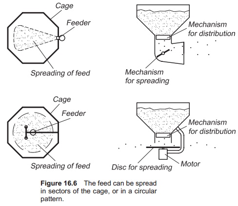
The sector feeding system normally consists of a vertical rotating plate or brush. When this rotates the feed is spread out in a sector in the cage or the pond. A circle feeding technique employs a centrifugal scattering system. The feed particles drop down from the distribution unit and hit a horizon-tally placed rotating disc. Because of the centrifugal forces the feed is spread out in a circle. The spreading unit may be integral part of the distribution system or it may be installed separately underneath the distribution unit. The velocity of the disc or plate determines the area of the sector or the circle where the feed is spread. However, a high velocity will increase the amount of breakage because the forces transferred from the spreading unit to the feed particles will increase.
Control units
The control unit manages the current to the motor on the dispensing system; this also controls the feeding. The simplest control unit sets the time interval between each meal and the running time, i.e. the length of each meal. Some control units are equipped with a photocell which only permits feeding during daylight. In more advanced units a daily increase in the running time may be added related to the expected growth rate of the fish in the production unit.
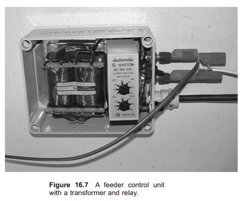
There may be an individual control unit for each feeder or the unit may control several feeders with the same feeding regime. There can also be one control unit with several channels, which means that it can control several feeders individually. The control unit can be a simple interval relay, where running time and time interval between each start are set (Fig. 16.7). Several relays may be set together in a multichannel control unit. The programmable logic controller (PLC) is a more advanced system carrying out the same tasks as a multichannel control unit. The input and output can be switched on or off, and it is quite easy to extend the system with more inputs and outputs. Each output channel can be programmed individually. In addition input signals can also be used to control the output signal. For instance, the output can only be started when the input signal from a light sensor registers that it is daylight; this means that feeding is only permitted during daylight.
A personal computer (PC) equipped with special ‘cards’ may also be used to control larger feeding systems. The PC can also collect data that can be used to control the feeding, such as water temperature and light intensity. PCs may also be used as a data logger to store, for instance, how much is fed every day.
Electric current
Both distribution and spreading mechanisms contain motors that normally need an external supply of power. This is normally electricity, either from a central electric power station (alternating current) or from batteries (direct current). A clock-work mechanism may also be used on small feeders. Direct current motors normally require a supply of 12 V or 24 V. Alternating current motors for feeders are either low voltage (12 V or 24 V) or normal voltage (110 V and 220 V). The advantage with high voltage is that thinner cabling is required and current loss in the cables is reduced, particularly when using long cables. The disadvantage is that normal voltage, high humidity and free water surfaces can be a dangerous combination. When using normal voltage it is therefore important to be careful when laying electric cables and ensure that the feeding system is correctly insulated and earthed to avoid jump sparks. Qualified professionals must perform such work.
Normally the mains voltage is used as the electricity source. If low voltage feeding systems are to be connected, the use of a transformer is necessary. If direct current is to be used, a rectifier is also needed.
If there is no electricity supply, for instance on a sea cage, either batteries or a diesel-powered electrical generator must be used. Use of batteries requires direct current motors on the feeder. In these cases the battery must be taken out regularly for recharging; solar panels or windmills may also be used to charge batteries.
Direct current motors used on feeders have the advantage that the speed of rotation of the motor can easily be regulated. By adding a variable resistance, the size of the incoming current that is running the motor will be regulated. Regulation of the speed of rotation will control the amount of feed coming from the feeders.
The motor output should be matched to the need for forces to run the distribution unit. Motors that are too powerful can result in more breakage of feed and are not recommended. The main reason for adding a larger motor is to avoid wedging so that the system is more reliable. Care should, however, be taken regarding the possibility of breakage when feeders are equipped with large motors.
Feeding systems
The term feeding system refers to a complete system that takes the feed directly from the feed silo or hopper, transports it to the fish production unit, and at the end distributes it to the fish. A complete feeding system may comprise three parts: a storage unit, a transport unit and a feed distribution unit. Today feeding systems can be divided into two types:
1. Systems where the feeder is centrally placed and feed is transported to the single fish production units (tanks, ponds or cages) through pipes, normally known as feeding systems.
2. Systems where the feeder is installed on a rail system that covers several units, normally called feeding robots.
Central feeding system
A central feeding system consists of storage silos, a sluice valve, tubes with a flow of water or air for transporting of feed, a selector valve, and eventu-ally a distribution unit (Fig. 16.8).
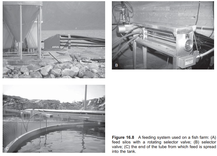
In this system the feed is delivered from the silo and into an auger that brings the feed particles into a hopper placed above a sluice valve. The sluice valve brings the feed particles from the hopper and into the pipes for further transport to the tanks or cages. To transport the feed particles, water or air is used as a medium and the sluice valve therefore also provides an air or water lock between the hopper and the transport medium; the sluice valve also represents the feed distribution unit.
Whether air or water is used as a transport medium, the velocity in the tubes is such that the feed particles will always stay in suspension. A blower or a pump ensures adequate velocity inside the tubes. During the past few years, air has become the major transport medium. After being trans-ported for a short distance in the pipes (some metres) the feed enters the selector valve whitch determines the production unit to which the feed portion is sent. There are several designs of selector valve; normally a rotating or a horizontal moving selector is used.
After the selector valve the feed is transported to the production unit through the tubes. In sea cages the tubes may be up to several hundred metres in length. The silos and selector valve may be placed on-shore or on a barge. If the system is for large cages, a unit for spreading the feed may also be included.
Correct design and use of the feeding system is important to avoid feed breakage and dust production. Important factors are air temperature, pick-up velocity, material in the pipes, design and use of the selector valve and pipeline routings.
A centrally placed computer controls this type of feeding system. The amount of feed to the different units can be set as fixed or be created automatically. Addition of the initial weight, water temperature, expected growth and mortality in to the computation ensures correct feeding. The computer also stores the inputs and is an important tool for production planning and production control.
Central feeding systems are also available for automatic feeding of moist feed.
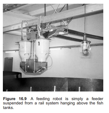
Feeding robots
Put simply, a feeding robot is a feeder suspended from a rail system hanging above the fish tanks (Fig. 16.9). A motor to push the feeder along the rail system is included. The rail system is laid over the production units and under the feed silos. The robot may have its docking station under the silos where it enters for automatic refilling with feed when the hopper on the feeder is empty. When the robot is feeding it moves along the rail until it hits a chip attached to the rail over each tank. Based on information in this chip, the feeder (robot) recognizes the tank. On the robot there is a computer where the amount to be fed to the actual tank is programed. When the robot hits the chip it will there-fore feed the programed amount of feed to the tank. After this it continues to the next tank, and so on. When the hopper on the robot is empty it auto-matically goes back to the silos for refilling. Several individual feeders can be attached to the same robot, so that it can deliver several feed sizes in the same operation. The electricity supply to the feeder and the motor may be an integrated part of the rail system, or it can be a battery which is recharged in the docking station. The great advantage with this system is that the same feeding mechanism can be used for feeding of several tanks. In this way more investment in this unit means it can be designed to feed more accurately. Accuracy can be improved by using double dispensers (multistage), as is in some robots.
Related Topics