Chapter: Mechanical : Manufacturing Technology : Turning Machines
Turning Machines
TURNING MACHINES
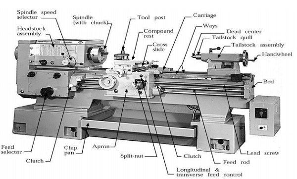
Center Lathes
A lathe is a machine tool that
rotates the work piece against a tool whose position it controls. The spindle
is the part of the lathe that rotates. Various work holding attachments such as
three jaw chucks, collets, and centers can be held in the spindle. The spindle
is driven by an electric motor through a system of belt drives and gear trains.
Spindle rotational speed is controlled by varying the geometry of the drive
train.
The tailstock can be used to support
the end of the workpiece with a center, or to hold tools for drilling, reaming,
threading, or cutting tapers. It can be adjusted in position along the ways to
accommodate different length workpieces. The tailstock barrel can be fed along
the axis of rotation with the tailstock hand wheel.
The carriage controls and supports the cutting tool. It
consists of:
A saddle that slides along the ways;
An apron that controls the feed mechanisms;
A cross slide that controls transverse motion of the tool (toward
or away from the operator);
A tool compound that adjusts to
permit angular tool movement; v a tool post that holds the cutting tools.
There are a number of different
lathe designs, and some of the most popular are discussed here.
Centre lathe
The basic, simplest and most versatile lathe.
This machine tool is manually
operated that is why it requires skilled operators. Suitable for low and medium
production and for repair works.
There are two tool feed mechanism
in the engine lathes. These cause the cutting tool to move when engaged.
The lead screw will cause the
apron and cutting tool to advance quickly. This is used for cutting threads,
and for moving the tool quickly.
The feed rod will move the apron
and cutting tool slowly forward. This is largely used for most of the turning
operations.
Work is held in the lathe with a number of methods.
Between
two centers. The work piece is driven by a device called a dog; the method is
suitable for parts with high length-to-diameter ratio.
A 3 jaw self-centering chuck is
used for most operations on cylindrical work parts. For parts with high
length-to-diameter ratio the part is supported by center on the other end.
Collet consists of tubular
bushing with longitudinal slits. Collets are used to grasp and hold bar stock.
A collet of exact diameter is required to match any bar stock diameter.
A face plate is a device used to grasp parts with irregular
shapes:
Taper turning methods
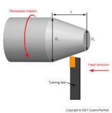
A taper is a conical shape.
Tapers can be cut with lathes quite easily. There are some common methods for
turning tapers on an center lathe,
Using a form tool: This type of
tool is specifically designed for one cut, at a certain taper angle. The tool
is plunged at one location, and never moved along the lathe slides. v Compound
Slide
Method: The compound slide is set
to travel at half of the taper angle. The tool is then fed across the work by
hand, cutting the taper as it goes. v Off-Set Tail Stock: In this method the
normal rotating part of the lathe still drives the workpiece (mounted between
centres), but the centre at the tailstock is offset towards/away from the cutting
tool. Then, as the cutting tool passes over, the part is cut in a conical
shape. This method is limited to small tapers over long lengths.The tailstock
offset h is defined by
h = Lsinα, where L is the length of work
piece,
and α is the half of the taper angle.
Thread
cutting methods
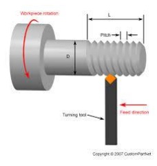
Different possibilities are
available to produce a thread on a lathe. Threads are cut using lathes by
advancing the cutting tool at a feed exactly equal to the thread pitch. The
single-point cutting tool cuts in a helical band, which is actually a thread.
The procedure calls for correct settings of the machine, and also that the
helix be restarted at the same location each time if multiple passes are
required to cut the entire depth of thread. The tool point must be ground so
that it has the same profile as the thread to be cut.
Another possibility is to cut
threads by means of a thread die (external threads), or a tap (internal
threads). These operations are generally performed manually for small thread
diameters.
Special Attachments
Unless a workpiece
has a taper machined onto it which perfectly matches the internal taper in the
spindle, or has threads which perfectly match the external threads on the
spindle (two conditions which rarely exist), an accessory must be used to mount
a workpiece to the spindle.
A workpiece may be
bolted or screwed to a faceplate, a large,
flat disk that mounts to the spindle. In the alternative, faceplate dogs may be used to secure the work to the faceplate.
A workpiece may be
mounted on a mandrel, or circular work clamped
in a three- or four-jaw chuck. For irregular shaped workpieces it is usual to use a
four jaw (independent moving jaws) chuck.
These holding devices mount directly to the Lathe headstock spindle.
In precision work,
and in some classes of repetition work, cylindrical workpieces are usually held
in a collet inserted into the spindle and secured either by a
draw-bar, or by a collet closing cap on the spindle. Suitable collets may also
be used to mount square or hexagonal workpieces. In precision tool making work
such collets are usually of the draw-in variety, where, as the collet is
tightened, the workpiece moves slightly back into the headstock, whereas for
most repetition work the dead length variety is preferred, as this ensures that
the position of the workpiece does not move as the collet is tightened.
A soft workpiece
(e.g., wood) may be pinched between centers by using a spur
drive at the headstock, which bites into the wood
and imparts torque to it.
Machining time
Machining time is the time when a machine is actually processing something.
Generally, machining time is the term used when there is a reduction in
material or removing some undesirable parts of a material. For example, in a
drill press, machining time is when the cutting edge is actually moving forward
and making a hole. Machine time is used in other situations, such as when a
machine installs screws in a case automatically.
One of the important aspects in manufacturing calculation is how
to find and calculate the machining time in a machining operation. Generally,
machining is family of processes or operations in which excess material is
removed from a starting work piece by a sharp cutting tool so the remaining
part has the desired geometry and the required shape. The most common machining
operations can be classified into four types: turning, milling, drilling
and lathe work.
Calculate Time for Turning

Capstan
versus turret

Capstan
Lathe Turret
Lathe
The term
"capstan lathe" overlaps in sense with the term "turret
lathe" to a large extent. In many times and places, it has been understood
to be synonymous with "turret lathe". In other times and places
it has been held in technical contradistinction to "turret lathe",
with the difference being in whether the turret's slide is fixed to the bed
(ram-type turret) or slides on the bed's ways (saddle-type turret). The
difference in terminology is mostly a matter of United Kingdom and
Common wealth usage versus United States usage. American usage tends to call them all "turret lathes".
The word
"capstan" could logically seem to refer to the turret itself, and to have
been inspired by the nautical capstan. A lathe turret with tools mounted in
it can very much resemble a nautical capstan
full of handspikes. This interpretation would lead
Americans to treat "capstan" as a synonym of "turret" and
"capstan lathe" as a synonym of "turret lathe". However,
the multi-spoked handles that the operator uses to advance the slide are also
called capstans, and they themselves also resemble the nautical capstan.
No distinction
between "turret lathe" and "capstan lathe" persists upon
translation from English into other languages. Most translations involve the
term "revolver", and serve to translate either of the English terms.
The words "turret" and
"tower", the former being a diminutive of the latter, come ultimately
from the Latin "turris", which means "tower", and the use
of "turret" both to refer to lathe turrets and to refer to gun
turrets seems certainly to have been inspired by its earlier connection to the
turrets of fortified buildings and to siege towers. The history of the rook in
chess is connected to the same history, with the French word for rook, tour,
meaning "tower".
It is an
interesting coincidence that the word "tour" in French can mean both
"lathe" and "tower", with the first sense coming ultimately
from Latin "tornus", "lathe", and the second sense coming
ultimately from Latin "turris", "tower". "Tour
revolver", "tour tourelle", and "tour tourelle
revolver" are various ways to say "turret lathe" in French.
Semi-automatic
Sometimes machines
similar to those above, but with power feeds and automatic turret-indexing at
the end of the return stroke, are called "semi-automatic turret
lathes". This nomenclature distinction is blurry and not consistently
observed. The term "turret lathe" encompasses them all. During the
1860s, when semi-automatic turret lathes were developed, they were sometimes
called "automatic". What we today would call "automatics",
that is, fully automatic machines, had not been developed yet. During that era
both manual and semi-automatic turret lathes were sometimes called "screw
machines", although we today reserve that term for fully automatic
machines.
Automatic
During the 1870s
through 1890s, the mechanically automated "automatic" turret lathe
was developed and disseminated. These machines can execute many part-cutting
cycles without human intervention. Thus the duties of the operator, which were
already greatly reduced by the manual turret lathe, were even further reduced,
and productivity increased. These machines use cams to automate the sliding
and indexing of the turret and the opening and closing
of the chuck. Thus, they execute the part-cutting cycle somewhat analogously to
the way in which an elaborate cuckoo clock performs an automated theater show.
Small- to medium-sized automatic turret lathes are usually called "screw
machines" or "automatic screw machines", while larger ones are
usually called "automatic chucking lathes", "automatic
chuckers", or "chuckers".
Related Topics