Chapter: Electrical and electronics : Circuit Theory : Transient Response For DC Circuits
Transient Response of RC Circuits
TRANSIENT RESPONSE OF RC CIRCUITS
Ideal and real capacitors: An ideal capacitor has an infinite dielectric resistance and plates (made of metals) that have zero resistance. However, an ideal capacitor does not exist as all dielectrics have some leakage current and all capacitor plates have some resistance. A capacitor’s of how much charge (current) it will allow to leak through the dielectric medium. Ideally, a charged capacitor is not supposed to allow leaking any current through the dielectric medium and also assumed not to dissipate any power loss in capacitor plates resistance. Under this situation, the model as shown in fig. 10.16(a) represents the ideal capacitor. However, all real or practical capacitor leaks current to some extend due to leakage resistance of dielectric medium. This leakage resistance can be visualized as a resistance connected in parallel with the capacitor and power loss in capacitor plates can be realized with a resistance connected in series with capacitor. The model of a real capacitor is shown in fig.
Let us consider a simple series RC−circuit shown in fig. 10.17(a) is connected through a switch ‘S’ to a constant voltage source .
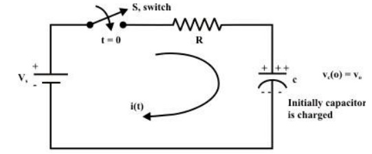
The switch ‘S’ is closed at time ‘t=0’ It is assumed that the capacitor is initially charged with a voltage and the current flowing through the circuit at any instant of time ‘’ after closing the switch is
Current decay in source free series RL circuit: -
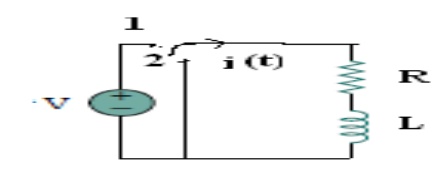
At t = 0- , , switch k is kept at position ‘a’ for very long time. Thus, the network is in steady state. Initial current through inductor is given as,
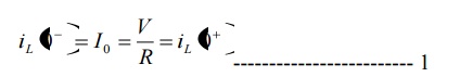
Because current through inductor can not change instantaneously
Assume that at t = 0 switch k is moved to position 'b'.
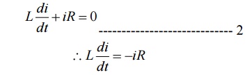
Applying KVL,
Rearranging the terms in above equation by separating variables
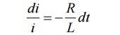
Integrating both sides with respect to corresponding variables
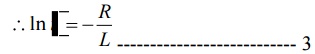
Where k’ is constant of integration.
To find- k’:
Form equation 1, at t=0, i=I0
Substituting the values in equation 3
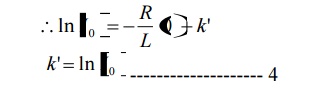
Substituting value of k’ from equation 4 in
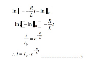
fig. shows variation of current i with respect to time
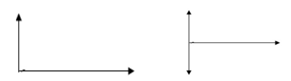
From the graph, H is clear that current is exponentially decaying. At point P on graph. The current value is (0.363) times its maximum value. The characteristics of decay are determined by values R and L which are two parameters of network.
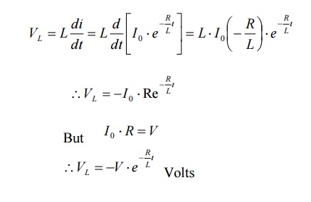
The voltage across inductor is given by
Related Topics