Chapter: Electrical machines : Transformer
Transformer Losses
Transformer Losses
1. Primary copper loss
2. Secondary copper loss
3. Iron loss
4. Dielectric loss
5. Stray load loss
These are explained in sequence below.
Primary and secondary copper losses take place in the respective winding resistances due to the flow of the current in them. The primary and secondary resistances differ from their d.c. values due to skin effect and the temperature rise of the windings. While the average temperature rise can be approximately used, the skin effect is harder to get analytically. The short circuit test gives the value of Re taking into account the skin effect.
The iron losses contain two components - Hysteresis loss and Eddy current loss. The Hysteresis loss is a function of the material used for the core.Ph = KhB1.6f For constant voltage and constant frequency operation this can be taken to be constant. The eddy current loss in the core arises because of the induced emf in the steel lamination sheets and the eddies of current formed due to it. This again producesa power loss Pe in the lamination.wheret is the thickness of the steel lamination used. As the lamination thickness is much smaller than the depth of penetration of the field, the eddy current loss can be reduced by reducing the thickness of the lamination. Present day laminations are of 0.25 mm thickness and are capable of operation at 2 Tesla.
These reduce the eddy current losses in the core. This loss also remains constant due to constant voltage and frequency of operation. The sum of hysteresis and eddy current losses can be obtained by the open circuit test. The dielectric losses take place in the insulation of the transformer due to the large electric stress. In the case of low voltage transformers this can be neglected. For constant voltage operation this can be assumed to be a constant. The stray load losses arise out of the leakage fluxes of the transformer. These leakage fluxes link the metallic structural parts, tank etc. and produce eddy current losses in them. Thus they take place ’all round’ the transformer instead of a definite place , hence the name ’stray’. Also the leakage flux is directly proportional to the load current unlike the mutual flux which is proportional to the applied voltage. Hence this loss is called ’stray load’ loss. This can also be estimated experimentally.
It can be modeled by another resistance in the series branch in the equivalent circuit. The stray load losses are very low in air-cored transformers due to the absence of the metallic tank. Thus, the different losses fall in to two categories Constant losses (mainly voltage dependant) and Variable losses (current dependant). The expression for the efficiency of the transformer operating at a fractional load x of its rating, at a load power factor of 2, can be written as losses and Pvar the variable losses at full load. For a given power factor an expression for in terms of the variable x is thus obtained. By differentiating with respect to x and equating the same to zero, the condition for maximum efficiency is obtained. The maximum efficiency it can be easily deduced that this maximum value increases with increase in power factor and is zero at zero power factor of the load. It may be considered a good practice to select the operating load point to be at the maximum efficiency point. Thus if a transformer is on full load, for most part of the time then the max can be made to occur at full load by proper selection of constant and variable losses. However, in the modern transformers the iron losses are so low that it is practically impossible to reduce the full load copper losses to that value. Such a design wastes lot of copper. This point is illustrated with the help of an example below. Two 100 kVA transformers And B are taken. Both transformers have total full load losses to be 2 kW. The break up of this loss is chosen to be different for the two transformers. Transformer A: iron loss 1 kW, and copper loss is 1 kW. The maximum efficiency of 98.04%occurs at full load at unity power factor. Transformer B: Iron loss =0.3 kW and full load copper loss =1.7 kW. This also has a full load of 98.04%. Its maximum occurs at a fractional load of q0.31.7 = 0.42. The maximum efficiency at unity power factor being at the corresponding point the transformer A has an efficiency of Transformer A uses iron of more loss per kg at a given flux density, but transformer B uses lesser quantity of copper and works at higher current density.
When the primary of a transformer is connected to the source of an ac supply and the secondary is open circuited, the transformer is said to be on no load. Which will create alternating flux. No-load current, also known as excitation or exciting current has two components the magnetizing component Im and the energy component Ie.
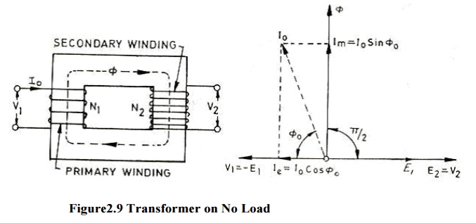
Im is used to create the flux in the core and Ie is used to overcome the hysteresis and eddy current losses occurring in the core in addition to small amount of copper losses occurring in the primary only (no copper loss occurs in the secondary, because it carries no current, being open circuited.) From vector diagram shown in above it is obvious that
1. Induced emfs in primary and secondary windings, and lag the main flux by and are in phase with each other.
2. Applied voltage to primary and leads the main flux by and is in phase opposition to
3. Secondary voltage is in phase and equal to since there is no voltage drop in secondary.
4.is in phase with and so lags
5.is in phase with the applied voltage .
6. Input power on no load = cosq
Transformer on Load
The transformer is said to be loaded, when its secondary circuit is completed through an impedance or load. The magnitude and phase of secondary current (i.e. current flowing through secondary) with respect to secondary terminals depends upon the characteristic of the load i.e. current will be in phase, lag behind and lead the terminal voltage respectively when the load is non-inductive, inductive and capacitive. The net flux passing through the core remains almost constant from no-load to full load irrespective of load conditions and so core losses remain almost constant from no-load to full load.
Secondary windings Resistance and Leakage Reactance In actual practice, both of the primary and have got some ohmic resistance causing voltage drops and copper losses in the windings. In actual practice, the total flux created does not link both of the primary and secondary windings but is divided into three components namely the main or mutual flux linking both of the primary and secondary windings, primary leakage flux linking with primary winding only and secondary leakage flux linking with secondary winding only.
The primary leakage flux is produced by primary ampere-turns and is proportional to primary current, number of primary turns being fixed. The primary leakage flux is in phase with and produces self inducedemf is in phase with and produces self inducedemf E given as 2f in the primary winding. The self inducedemf divided by the primary current gives the reactance of primary and is denoted by .
i.e. E = 2fπ
Related Topics