Chapter: Power Electronics : Power Semi Conductor Devices
Thyristor Protection and Gate Protection
Thyristor Protection
Over Voltage Protection
Over voltage occurring during the switching operation causes the failure of SCR.
Internal Overvoltage
It is due to the operating condition of SCR.During the commutation of SCR ,when the anode current decays to zero anode current reverses due to stored changes. First the reverse current rises to peak value, then reverse current reduces abruptly with large di/dt.
. During series inductance of SCR large transient large voltage i.e Ldidt/ is generated.
External Over Voltage
This is due to external supply and load condition. This is because of
1. The interruption of current flow in an inductive circuit.
2. Lightening strokes on the lines feeding the thyristor systems.
Suppose a SCR converter is fed from a transformer, voltage transient occur when transformer primary will energise or de-energised.
This overvoltages cause random turn ON of a SCR. The effect of overvoltage is minimized using
1. RC circuits
2. Non linear resistor called voltage clamping device.
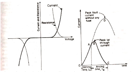
Voltage clamping device is a non linearresistor.It is connected between cathode and anode of SCR. The resistance of voltage clamping device decreases with increasing voltages. During normal working condition Voltage clamping (V.C) device has high resistance, drawing only leakage current. When voltage surge appears voltage clamping device offers a low resistance and it create a virtual short circuit across the SCR. Hence voltage across SCR is clamped to a safe value.
When surge condition over voltage clamping device returns to high resistance state. e.g. of voltage clamping device
1.Seleniumthyrector diodes
2.Metal Oxide varistors
3.Avalanche diode supressors
1. Over Current Protection
Long duration operation of SCR, during over current causes the
1.junction temp. of SCR to rise above the rated value,causing permanent damage to device.
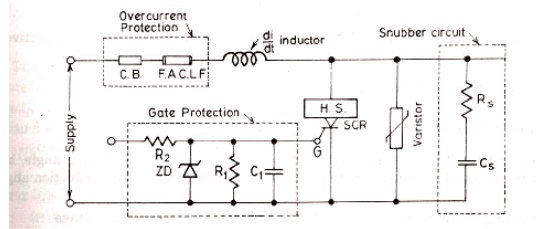
SCR is protected from overcurrent by using 1.Circuit breakers
2.Fast acting fuses
Proper co-ordination is essential because
1..fault current has to be interrupted before SCR gets damaged.
2. Only faulty branches of the network has to be replaced. In stiff supply network, source has negligible impedance. So in such system the magnitude and rate of rise of current is not limited. Fault current hence junction temp rises in a few miliseconds.
POINTS TO BE NOTED-
1. Proper coordination between fast acting fuse and thyristor is essential.
2. The fuse is always rated to carry marginal overload current over definite period.
3. The peak let through current through SCR must be less than sub cycle rating of the SCR.
4. The voltage across the fuse during arcing time is called arcing or recovery voltage and is equal to sum of the source voltage and emf induced in the circuit inductance during arcing time.
5. On abrupt interruption of fuse current, induce emf would be high, which results in high arcing voltage.
Circuit Breaker (C.B)
C.B. has long tripping time. So it is used for protecting the device against continuous overload current or against the surge current for long duration. In order that fuse protects the thyristor realiably the I2t rating of fuse current must be less than that of SCR.
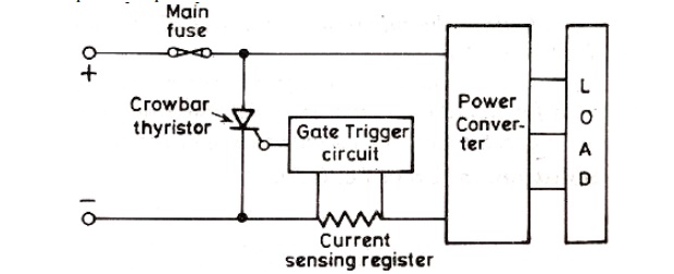
ELECTRONIC CROWBAR PROTECTION
For over current protection of power converter using SCR, electronic crowbar are used. It provide rapid isolation of power converter before any damage occurs.
HEAT PROTECTION-
To protect the SCR
1. From the local spots
2. Temp rise
SCRs are mounted over heat sinks.
Gate Protection
Gate circuit should also be protected from
1. Overvoltages
2. Overcurrents
Overvoltage across the gate circuit causes the false triggering of SCR
Overcurrent raise the junction temperature. Overvoltage protection is by zener diode across the gate circuit.
Related Topics