Chapter: Analog and Digital Communication
Theory of Amplitude Modulation
THEORY OF AMPLITUDE MODULATION
Amplitude
Modulation
Amplitude
Modulation is the changing the amplitude of the carrier signal with respect to
the instantaneous change in message signal.
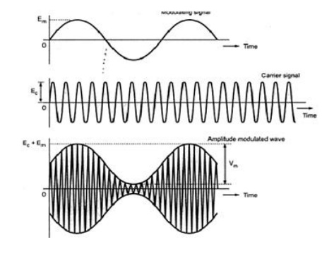
The amplitude modulated wave form, its envelope and its frequency spectrum and bandwidth.
Fig (a) Sinosoidal modulation signal (b)High frequency carrier (c)
AM signal.
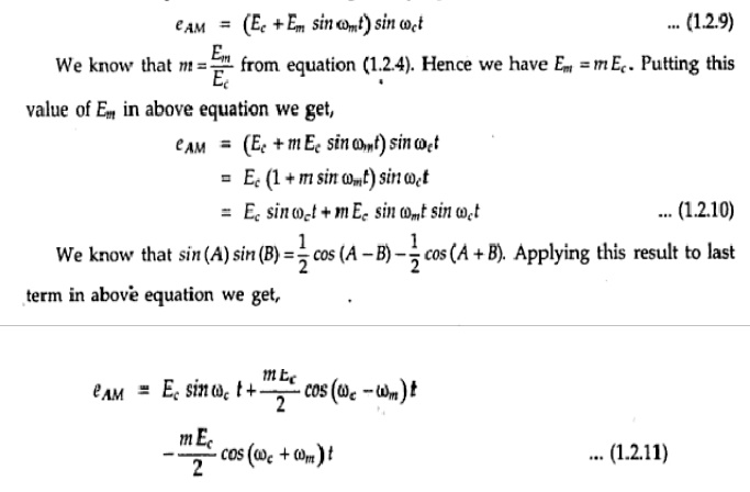
Using the above
mathematical expressions for modulating and carrier signals, we can create a
new mathematical expression for the complete modulated wave. It is given as,
Modulation Index and
Percent Modulation
The ratio of maximum amplitude of modulating signal to maximum amplitude carrier signal is called modulation index. i.e.,
Value of Em
must be less than value of Ec to avoid any distortion in the
modulated signal. Hence maximum value of modulation index will be equal to 1
when Em=Ec. Minimum value will be zero. If modulation
index is higher than 1, then it is called over
modulation. Data is lost in such case. When modulation index is expressed
in percentage , it is also called percentage modulation.
Calculation
of modulation index from AM waveform:
Fig 1.2.2 shows the AM
waveform. This is also called time domain representation of AM signal.
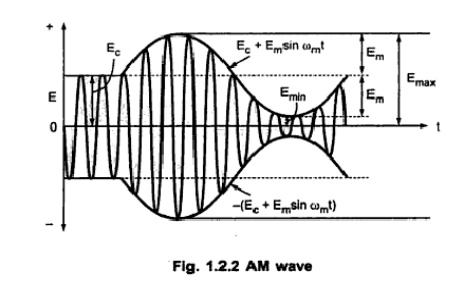
It is clear from the
above signal that the modulating signal rides upon the carrier signal. From
above figure we can write,
Frequency
Spectrum and Bandwidth
The modulated carrier
has new signals at different frequencies, called side frequencies or sidebands.
They occur above and below the carrier frequency.
Consider the expression
of AM wave given by equation (1.2.3),I.e.,
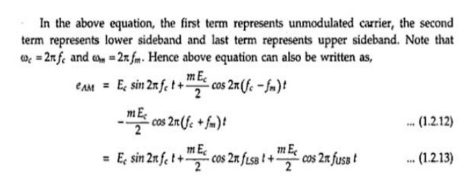
From this equation we
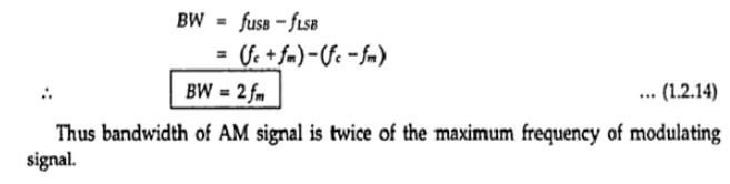
can prepare the frequency spectrum of AM wave as shown below in fig. 1.2.3.
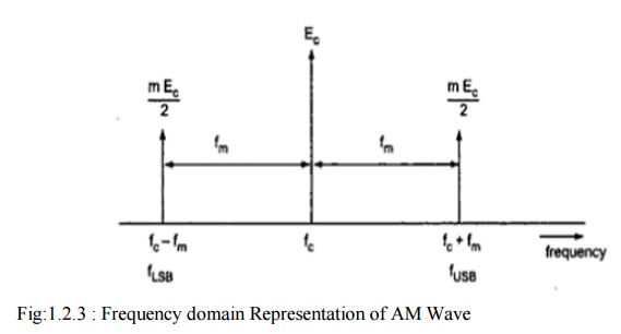
Fig:1.2.3 : Frequency
domain Representation of AM Wave
This contains full
carrier and both the sidebands, hence it is also called Double Sideband Full
Carrier (DSBFC) system. We will be discussing this system, its modulation
circuits and transmitters next, in this section.
We know that bandwidth
of the signal can be obtained by taking the difference between highest and
lowest frequencies. From above figure we can obtain bandwidth of AM wave as,
Amplitude
Modulation of Power distribution:
AM Power Distribution:
AM signal has three
components : Unmodulated carrier, lower sideband and upper sideband. Hence
total power of AM wave is the sum off carrier power Pe and powers in the two
sidebands PLSB. i.e.,
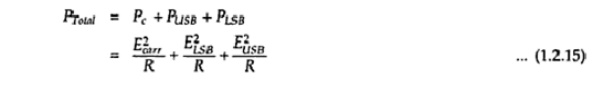
Here all the three
voltages are rms values and R is characteristic impedence of antenna in which
the power is dissipated. The Carrier Poweer is,
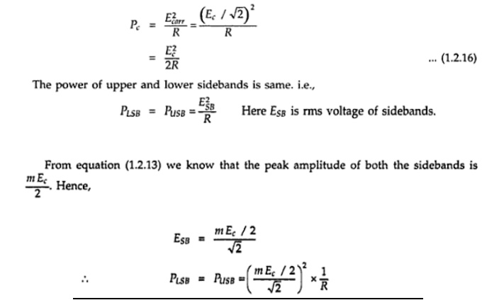
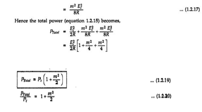
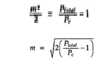
This
equation relates total power of AM wave to carrier power, Maximum Value of
modulation index, m=1 to avoid distortion. At this value of modulation index,
Ptotal = 1.5 Pc. From the above equation we have
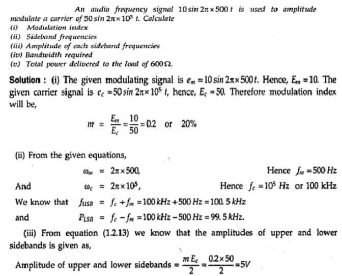
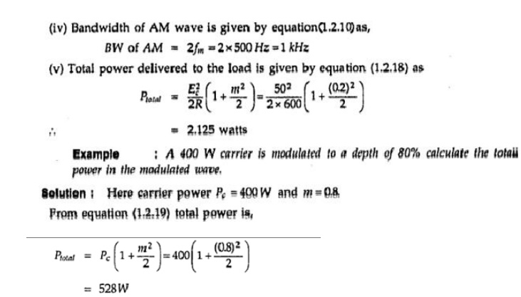
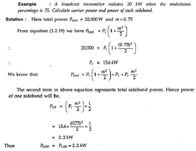
Example Problems:
Related Topics