Chapter: Satellite Communication : Space Segment and Satellite Link Design
The Uplink
The Uplink
The
uplink of a satellite circuit is the one in which the earth station is
transmitting the signal and the satellite is receiving it specifically that the
uplink is being considered.
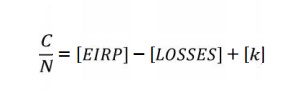
In
this Eq the values to be used are the earth station EIRP, the satellite
receiver feeder losses, and satellite receiver G/T. The free-space loss and
other losses which are frequency-dependent are calculated for the uplink
frequency.
1. Input backoff
Number
of carriers are present simultaneously in a TWTA, the operating point must be
backed off to a linear portion of the transfer characteristic to reduce the
effects of inter modulation distortion. Such multiple carrier operation occurs
with frequency- division multiple access (FDMA), which is described in Chap.
14. The point to be made here is that backoff (BO) must be allowed for in the
link- budget calculations.
Suppose
that the saturation flux density for single-carrier operation is known. Input
BO will be specified for multiple-carrier operation, referred to the single-
carrier saturation level. The earth-station EIRP will have to be reduced by the
specified BO, resulting in an uplink value of
[EIRP]U
= [EIRPS]U + [BO]i
2. The earth
station HPA
The
earth station HPA has to supply the radiated power plus the transmit feeder
losses, denoted here by TFL, or [TFL] dB. These include waveguide, filter, and
coupler losses between the HPA output and the transmit antenna. Referring back
to Eq. (12.3), the power output of the earth station itself may have to
transmit multiple carriers, and its output also will require back off, denoted
by [BO]HPA. The earth station HPA must be rated for a saturation power output
given by
[PHPA,sat]
= [PHPA] + [BO]HPA
Related Topics