Chapter: High Voltage Engineering : Over Voltages in Electrical Power Systems
Switching Surge Test Voltage Characteristics
Switching Surge Test Voltage Characteristics
Switching surges assume great importance for designing insulation of overhead lines operating at voltages more than 345 kV. It has been observed that the flashover voltage for various geometrical arrangements under unidirectional switching surge voltages decreases with increasing the front duration of the surge and the minimum switching surge corresponds to the range between 100 and 500 ÎĽsec. However, time to half the value has no effect as flashover takes place either at the crest or before the crest of the switching surge. Fig.1.8 gives the relationship between the critical flashover voltage per meter as a function of time to flashover for on a 3 m rod-rod gap and a conductor-plane gap.
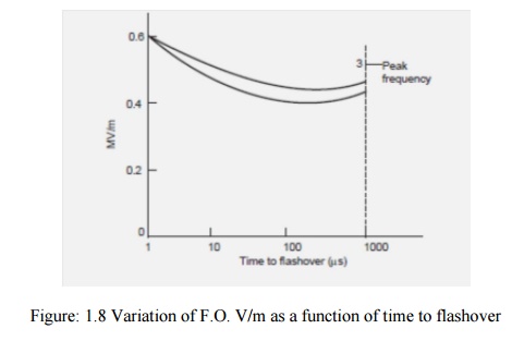
It can be seen that the standard impulse voltage (1/50 ÎĽ sec) gives highest flashover voltage and switching surge voltage with front time varying between 100 to 500 ÎĽ sec has lower flashover voltages compared to power frequency voltage. The flashover voltage not only depends upon the crest time but upon the gap spacing and humidity for the same crest time surges.
It has been observed that the switching surge voltage per meter gap length decreases drastically with increase in gap length and, therefore, for ultra high voltage system, costly design clearances are required. Therefore, it is important to know the behavior of external insulation with different configuration under positive switching surges as it has been found that for nearly all gap configurations which are of practical interest positive switching impulse is lower than the negative polarity switching impulse.
It has also been observed that if the humidity varies between 3 to 16 gm/m3, the breakdown voltage of positive and gaps increases approximately 1.7% for 1 gm/m3 increase in absolute humidity. For testing purposes the switching surge has been standardized with wave front time 250 ÎĽ deceit is known that the shape of the electrode has a decided effect on the flashover voltage of the insulation.
Lot of experimental work has been carried on the switching surge flash over voltage furlong gaps using rod-plane gap and it has been attempted to correlate these voltages with switching surge flash over voltage of other configuration electrodes. Several investigators have shown that if the gap length varies between 2 to 8 m, the 50% positive switching surge flash over for any configurations given by the expression
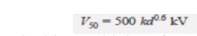
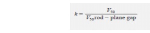
where d is the gap length in meters, k is the gap factor which is a function of electrode geometry. Forrod-plane gaps K = 1.0. Thus K represents a proportionality content and is equal to 50% flash overvoltage of any gap geometry to that of a rod-plane gap for the same gap spacing
i.e., The expression for V50 applies to switching impulse of constant crest time. A more general expression which applies to longer times to crest has been proposed as follows :

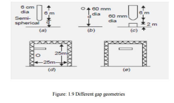
here K and d have the same meaning as in the equation above. The gap factor K depends mainly on the gap geometry and hence on the field distribution in the gap. Shown in Fig 1.9
Related Topics