Chapter: Civil : Strength of Materials : Energy Principles
Strength of Materials - Energy Principles
Energy Principles
Strain Energy, Proof Stress
Whenever a body is strained, the energy is
absorbed in the body. The energy which is
absorbed in the body due to straining effect is known as strain energy.
The strain energy stored in the body is
equal to the work done by the applied load in stretching the body.
Proof Stress
The stress induced in an elastic body when it
possesses maximum strain energy is termed as
its proof stress.
Derive the expression for strain energy in
Linear Elastic Systems for the following cases. (i) Axial loading (ii) Flexural Loading (moment
(or) couple)
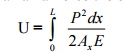
(i)Axial Loading
Let us
consider a straight bar of Length L, having uniform cross- sectional area A. If
an axial load P is applied gradually,
and one,ifstoredthe bar as strain energy
(U) in the body, will be equal to average force (1/2 P) multiplied by the deformation ?.
Thus U
= � P. ?
But
? = PL
/ AE
U
= � P. PL/AE = P2 L / 2AE
---------- (i)
If, however the bar has variable area of cross
section, consider a small of length dx and area
of cross section Ax. The strain energy dU stored in this small element
of length dx will be, from equation (i)
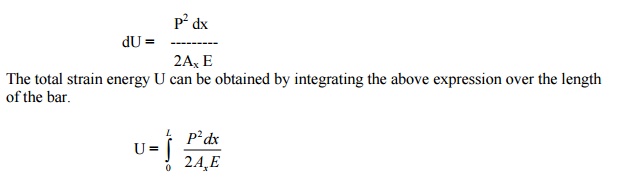
The total strain energy U can be obtained by
integrating the above expression over the length of the bar.
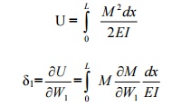
(ii) Flexural Loading (Moment or couple
)
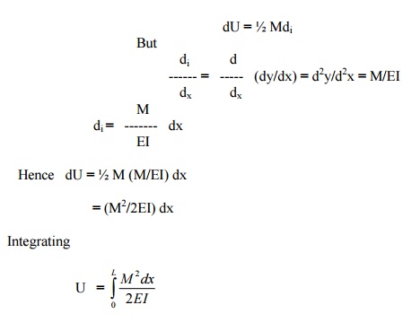
Let us now consider a member of length L
subjected to uniform bending moment M.
Consider an element of length dx and let di be the change in
the slope of the element due to applied
moment M. If M is applied gradually, the strain energy stored in the small
element will be
RESILIENCE
The resilience is defined as the capacity of a
strained body for doing work on the removal of
the straining force. The total strain energy stored in a body is
commonly known as resilience.
PROOF RESILIENCE
The proof resilience is
defined as the quantity of strain energy stored in a body when strained up to
elastic limit. The maximum strain energy stored in a body is known as proof
resilience.
MODULUS OF RESILIENCE
It is defined
as the proof resilience of a material per unit volume.
Modulus of resilience = Proof resilience / Volume of the body
Two methods for analyzing the statically
indeterminate structures.
a. Displacement method (equilibrium method
(or) stiffness coefficient method
b.Force
method (compatibility method (or) flexibility coefficient method)
Castigliano's first
theorem second Theorem
First Theorem.
It states that the deflection caused by any
external force is equal to the partial derivative of the strain energy with respect to that force.
Second Theorem
It states that 'If U is the total strain
ene external force; its magnitude is
always a minimum.
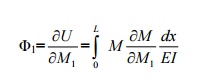
Castigliano's first theorem:
It states
that the deflection caused by any external force is equal to the partial
derivative of the strain energy with
respect to that force. A generalized statement of the theorem is as follows:
' If
there is any umelastic under the action of system asetofaforcesin equ
W1
, W2, W3 ����.Wn and corresponding1,?2,?3����.displacements?andset
of moments M1
, M2, M3���Mn
and corresponding1,2,?3,?��..rotations,then?
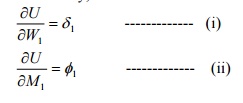
the partial derivative of the total strain
energy U with respect to any one of the forces or moments taken individually would yield its
corresponding displacements in its direction of
actions.'
Expressed mathematically,
Proof:
Consider an
elastic body as show in fig subjected to loads W1, W2, W3
���etc.
each applied independently. Let the body be
supported at A, B etc. The reactions RA ,RB etc do not work while the body deforms because
the hinge reaction is fixed and cannot move
(and therefore the work done is zero) and the roller reaction is
perpendicular to the displacements of the roller. Assuming that displacements
of the points of loading will be linear functions of the loads and the
principles of superposition will hold.
Let1, ??2, ?3��� etc be the
deflections of po loads at these points. The total strain energy U is then
given by
U
= � (W1?1 + W2 ?2 + ���.)--------- (iii)
Let the load W1 be increased by an
amount dW1, after the loads have been applied. Due to this, there will be small changes in the
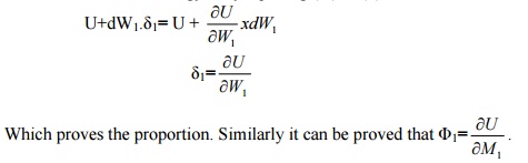
deformation of the body, and the strain energy will be increased slightly by an amount dU.
expressing this small increase as the rate of change of U with respect to W1 times dW1,
the new strain energy will be
On the assumption that the principle of
superposition applies, the final strain energy does not depend upon the order in which the forces
are applied. Hence assuming that dW1 is acting on the body, prior to the application
of W1, W2, W3 ���etc, the deflection infinitely small and the corresponding strain
energy of the second order can be neglected.
Now when W1,
W2, W3 ���etc,
are applied 1still
actinginitially), (withthepointsdW1, 2,
3 etc will move through 1 ,?
?2, ?3��� etc.
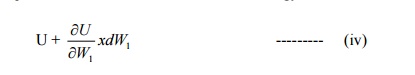
in the directio energy will be given as above. Due to the
application of W1,
rides through1and a d
produces the external work increment dU = dW1 . ?1. Hence
the strain energy, when the loads are
applied is
U+dW1.1?
----------- (v)
Since the final strain energy is by equating
(iv) & (v).
Deflection
of beams by castigliano's first theo
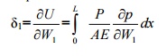
If a member carries an axial force the
energies stored is given by
In the above expression, P is the axial
force in the member and is the function of external load W1, W2,W3 etc. To compute1 in the the
direction of deflection W1
If the strain energy is due to bending
and not due to axial load
If no load is acting at the point where
deflection is desired, fictitious load W is applied at the point in the direction where the deflection
is required. Then after differentiating but before integrating the fictitious load is set to
zero. This method is sometimes known as the fictitious load method.1 isIfrequiredthein
directionrotationofM1. ?
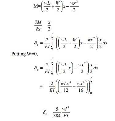
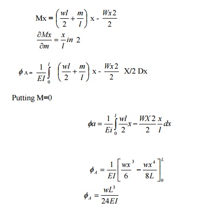
Calculate the central deflection and the slope
at ends of a simply supported beam carrying
a UDL w/ unit length over the whole span.
Solution:
a) Central deflection:
Since no point load is acting at the center
where the deflection is required, apply the
fictitious load W, then the reaction at A and
Consider a
section at a distance x from A.
Bending moment at x,
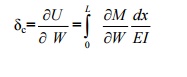
b) Slope at ends
To obtain the slope at the end A, say apply a
frictions moment A as shown in fig. The reactions at A and B will be
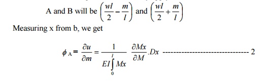
Where Mx is the moment at a point distant x
from the origin (ie, B) is a function of M.

Castigliano's
second theorem:
It states that the strain energy of a
linearly elastic system that is initially unstrained will have less strain
energy stored in it when subjected to a total load system than it would have if
it were self-strained.

For example, if lis small strain (or) displacement, within the
elastic limit in the direction of the
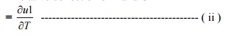
redundant force T,
?=0
when the redundant supports do not yield (or) when there is no initial lack of
fit in the redundant members.
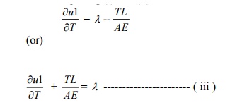
Proof:
Consider a redundant frame as shown in fig.in
which Fc is a redundant member of
geometrical length L.Let the actual length of the member Fc be (L- ?), ? being the initial lack of fit.F2 C
represents thus the actual length (L- ?)
of the member. When it is fitted to the truss,
the member will have to be pulled such that F2 and F coincide.
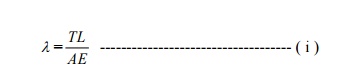
According to Hooke?s law
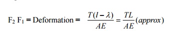
Where T is the force (tensile) induced in the
member.
Hence FF1=FF2-F1
F2
Let the
member Fc be removed and consider a tensile force T applied at the corners F
and C.
FF1 = relative deflection of F and
C
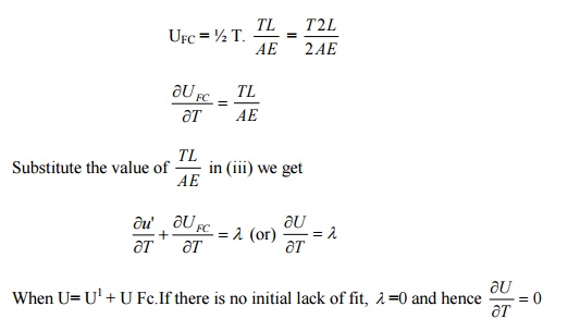
According to castigliano?s is the strain
energy first of the whole theorem frame except wher that of the member Fc.
Equating (i) and (ii) we get
To strain energy stored in the member Fc due
to a force T is
Note:
i)
Castigliano?s theorem ofthe for
analysisminimumofstatically strai
indeterminate beam ands portal tranes,if the degree of redundancy is not
more than two.
ii)
If the degree of redundancy is more than two,
the slope deflection method or the moment distribution method is more convenient.
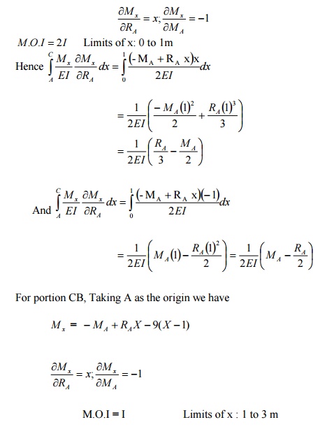
A beam AB of span 3mis fixed at both the ends
and carries a point load of 9 KN at C distant 1m from A. The M.O.I. of the portion AC of the
beam is 2I and that of portion CB is I. calculate the fixed end moments and reactions.
Solution:
There are four unknowns Ma, Ra,
Mb and Rb.Only two equations of static are available (ie) �v
=0 and �M =0
This problem
is of second degree indeterminacy.
First choose
MA and MB as redundant.
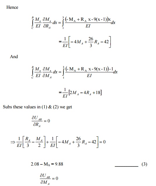
1) For portion AC:
Taking A as
the origin
Mx
= -MA + RA x
To find MB, take moments at B, and
apply the condition �M
=0 there. Taking clockwise moment as positive and anticlockwise moment
as negative. Taking MB clockwise, we have
MB
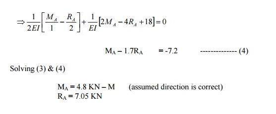
-MA =RA (3) -9x2 = 0
MB
-4.8 + (7.05x 3) -18 = 0
MB
= 1.65 KN -m (assumed direction is correct)
To find RB
Apply �V
=0 for the whole frame.
RB
= 9 -RA = 9-7.05 = 1.95 KN
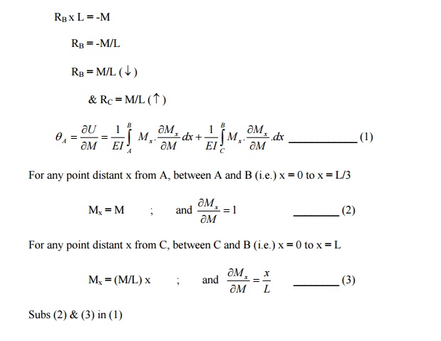
Using Castigliano's First
Theorem,rotationofthe determine
overhanging end A of the beam loaded.
Sol:
Rotation of A:
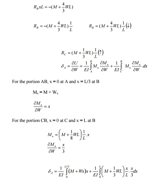
RB
x L = -M
RB
= -M/L
RB
= M/L ( �)
& RC
= M/L ( �)
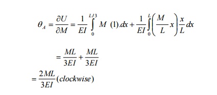
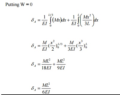
b) Deflection of A:
To find the
deflection at A, apply a fictitious load W at A, in upward direction as
shown in fig.
PRINCIPLE OF VIRTUAL WORK
It states that the workdone on a structure by
external loads is equal to the internal energy
stored in a structure (Ue = Ui)
Work of
external loads = work of internal loads
STRAIN ENERGY STORED IN
A ROD OF LENGTH L AND AXIAL RIGIDITY AE TO
AN AXIAL FORCE P
Strain energy stored
U=
P2 L / 2AE
STATE THE VARIOUS
METHODS FOR COMPUTING THE JOINT DEFLECTION OF
A PERFECT FRAME
1.
The Unit Load method
2.
Deflection
by Castigliano?s First
Theore
3.
Graphical method : Willot -Mohr Diagram
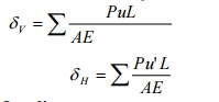
STATE THE DEFLECTION OF THE JOINT DUE TO
LINEAR DEFORMATION
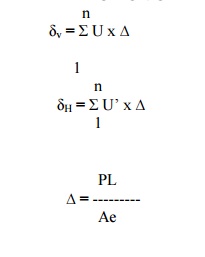
U= vertical
deflection
U?= horizontal
deflection
THE DEFLECTION OF JOINT DUE TO
TEMPERATURE VARIATION n
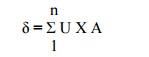
= U1?1
+ U2 ?2 + ����+n?n
U
If the change in length (?) of certainembers
memb will be substituted as zero in the
above equation.
STATE THE DEFLECTION OF
A JOINT DUE TO LACK OF FIT n
= U1?1
+ U2 ?2 + ����+n?n
U
If there is only one member having lack 1of,the
deflectionfit of?a particular joint will be
equal to U1?1.
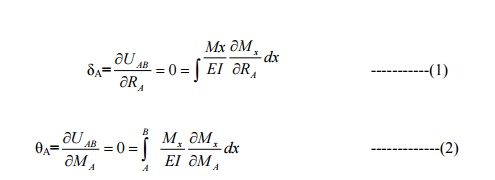
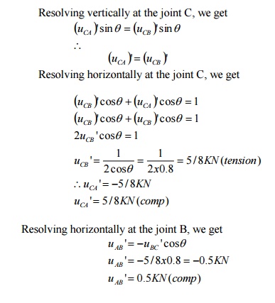
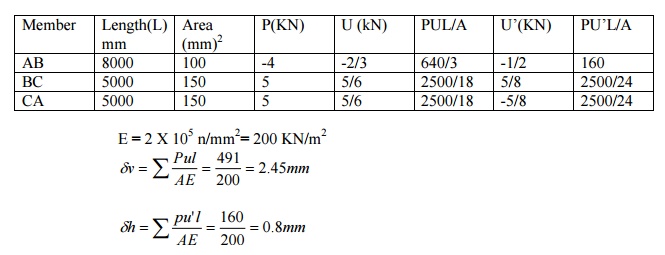
Determine the vertical and horizontal
displacements of the point C of the pin-jointed frame shown in fig. The cross sectional area of AB
is 100 sqmm and of AC and BC 150 mm2 each. E= 2 x 10 5 N/mm2. (By
unit load method)
Sol:
The vertical and horizontal deflections of the
joint C are given by
A) Stresses due to External Loading:
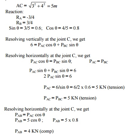
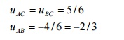
B) Stresses due to unit vertical load at C:
Apply unit
vertical load at C. The Stresses in each member will be 1/6 than of those obtained due to external load.
C) Stresses due to unit horizontal load at C:
Assume the
horizontal load towards left as shown in fig.
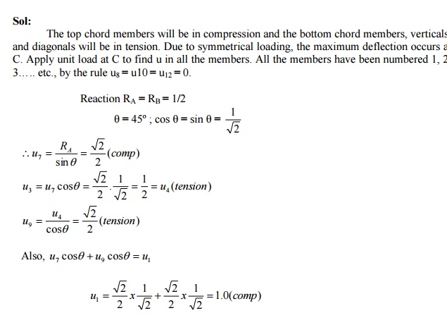
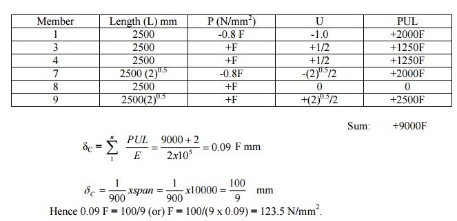
The frame shown in fig. Consists of four
panels each 25m wide, and the cross sectional
areas of the member are such that, when the frame carries equal loads at
the panel points of the lower chord, the
stress in all the tension members is f n/mm2 and the stress in all
the comparison members of 0.8 f N/mm2.Determine
the values of f if the ratio of the maximum
deflection to span is 1/900 Take E= 2.0 x 10⁵ N/mm2.
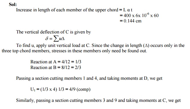
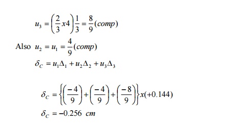
Determine the vertical deflection of the joint
C of the frame shown in fig. due to
temperature rise of 60� F in the upper chords only. The coefficient of
expansion = 6.0 x 10⁻⁶ per 1�
F and E = 2 x 10 6 kg /cm2.
Using the principle of least work, analyze the
portal frame shown in Fig. Also plot the
B.M.D.
Sol:
The support is hinged. Since there are two
equations at each supports. They are HA, VA, HD, and VD. The available equilibrium equation is
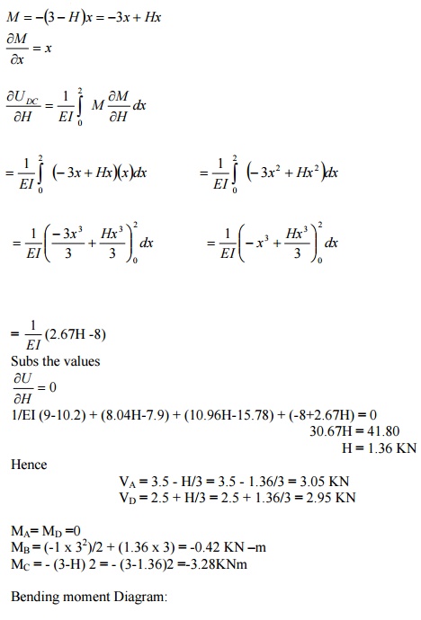
three. (i.e.) �M
=0, �H
=0, �V
=0 .
\
The structure is statically indeterminate to first degree. Let us treat the
horizontal H ( �) at A as redundant. The horizontal reaction at D
will evidently be = (3-H) ( �).
By taking moments at D, we get
(VA
x 3) + H (3-2) + (3 x 1) (2 -1.5) -(6 x 2) = 0
VA
= 3.5 -H/3
VD
= 6 -VA = 2.5 + H/3
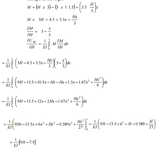
By the
theorem of minimum strain energy,
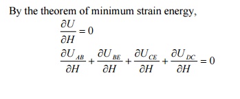
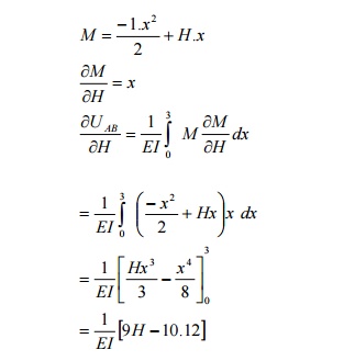
(1)For member AB:
Taking A as
the origin.
(2) For the member BE:
Taking B as the origin.
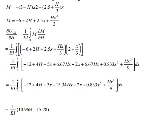
(3) For the member CE:
Taking C as
the origin
(4) For the member DC:
Taking D as
the origin
A
simply supported beam of span 6m is subjected to a concentrated load of 45 KN
at 2m from the left support. Calculate
the deflection under the load point. Take E = 200 x 106 KN/m2 and I = 14 x 10-6
m4.
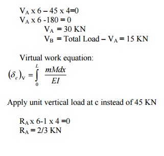
RB
= Total load -RA = 1/3 KN
Virtual Moment:
Consider
section between AC
M1
= 2/3 X1 [limit 0 to 2]
Section
between CB
M2
= 2/3 X2-1 (X2-2 ) [limit 2 to 6 ]
Real Moment:
The internal
moment due to given loading
M1=
30 x X1
M2
= 30 x X2 -45 (X2 -2)
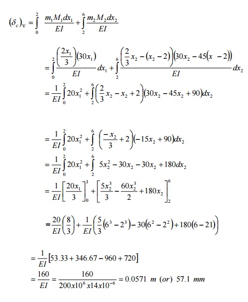
The deflection under the load = 57.1 mm
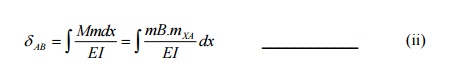
Define and prove the Maxwell's reciprocal theorem
The Maxwell?s
reciprocal 'The work theorem done stated by the asf due to displacements caused
by a second system of loads equals the work done by the second system of loads
due to displacements caused by the first system o loads".
Maxwell?s theorem of reciprocal deflection has the following three versions:
1. The deflection at A due to unit force at B is
equal to deflection at B due to unit force at A.
?AB
= ?BA
2. The slope
at A due to unit couple at B is equal to the slope at B due to unit couple A
?AB
= ?BA
3. The slope
at A due to unit load at B is equal to deflection at B due to unit couple.
Proof:
By unit load
method,
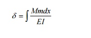
Where,
M= bending
moment at any point x due to external load.
m= bending moment at any point x due to unit
load applied at the point where
deflection is required.
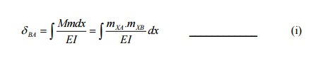
Let mXA=bending moment at any point x due
to unit load at A
Let mXB = bending moment at any point x
due to unit load at B.
When unit load (external load) is applied at A,
M=mXA
To find
deflection at B due to unit load at A, apply unit load at B.Then m= mXB
Hence,
Similarly,
When unit
load (external load) is applied at B, M=mXB
To find the
deflection at A due to unit load at B, apply unit load at A.then m= mXA
Comparing (i)
& (ii) we get
?AB = BA?
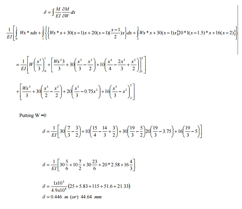
Using Castigliano's theorem, determine the
de shown in the fig. Take EI = 4.9 MN/m2.
Solution:
Apply dummy load W at B. Since we have to
determine the deflection of the free end.
Consider a section xx at a distance x from B. Then
M
x =Wx +30(x-1)+20 *1* (x-1.5)+16(x-2)
A
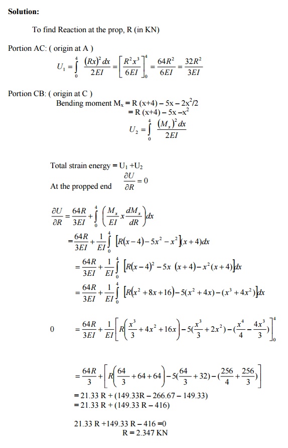
cantilever, 8m long, carrying a point loads 5 KN at the center and an udl of 2
KN/m for a length 4m from the end B. If
EI is the flexural rigidity of the cantilever find the reaction at the prop.
'
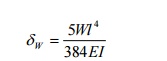
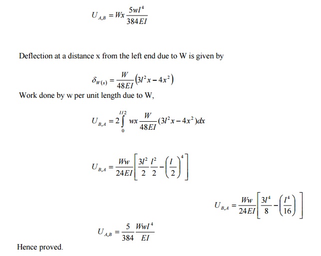
A simply supported beam of span L is carrying a concentrated load W at the
centre and a uniformly distributed load
of intensity of w per unit leng the
centre of the beam.
Solution:
Let the load
W is applied first and then the uniformly distributed load w.
Deflection
due to load W at the centre of the beam is given by
Hence work done by W due to w is given by:
STATE THE DIFFERENCE
BETWEEN UNIT LOAD AND STRAIN ENERGY
METHOD IN THE DETERMINATION OF STRUCTURES.
In strain energy method, an imaginary load P
is applied at the point where the deflection is
desired to be determined. P is equated to zero in the final step and the
deflection is obtained.
In the Unit Load method, a unit load (instead
of P) is applied at the point where the deflection is desired.
STATE THE ASSUMPTIONS MADE IN THE UNIT LOAD
METHOD
2.
The external and internal forces are in
equilibrium
3.
Supports are rigid and no movement is possible
4.
The material is strained well within the
elastic limit.
5.
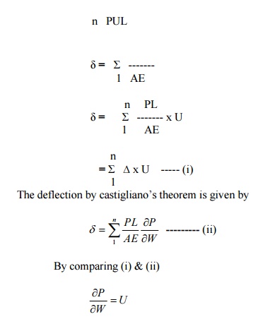
LOAD METHOD
The deflection by the unit load method is given by n
PUL
STATE MAXWELL'S RECIPROCAL THEOREM
The Maxwell?s Reciprocal theorem states
as due to displacements caused by a
second system of loads equals the work done by the second system of loads due to displacements caused by the
first system of loads.
DEGREE OF REDUNDANCY
A frame is said to be statically indeterminate
when the no of unknown reactions or stress
components exceed the total number of condition equations of
equilibrium.
PERFECT FRAME
If the number of unknowns is equal to the
number of conditions equations available, the frame is said to be a perfect frame.
STATE THE TWO TYPES OF STRAIN ENERGIES
c. strain energy of
distortion (shear strain energy)
d.strain
energy of uniform compression (or) tension (volumetric strain energy)
STATE IN WHICH CASES, CASTIGLIANO'S THEOREM
CAN
1.
To determine the displacements of complicated
structures.
2.
To find the deflection of beams due to
shearing (or) bending forces (or) bending moments are unknown.
3.
To find the deflections of curved beams
springs etc.
Related Topics