Chapter: Microprocessor and Microcontroller : Micro Controller Programming & Applications
Stepper Motor Interfacing with 8051 Micro Controller
Stepper Motor Interfacing
This
section begins with an overview of the basic operation of stepper motors. Then
we describe how to interface a stepper motor to the 8051. Finally, we use
Assembly language programs to demonstrate control of the angle and direction of
stepper motor rotation.
Stepper motors:
A stepper
motor is a widely used device that translates electrical pulses into mechanical
movement. In applications such as disk drives, dot matrix printers, and
robotics, the stepper motor is used for position control. Stepper motors
commonly have a permanent magnet rotor (also called the shaft) surrounded by a
stator. There are also steppers called variable reluctance stepper motors that
do not have a PM rotor. The most common stepper motors have four stator
windings that are paired with a center-tapped common as shown in Figure 5.11.
This type of stepper motor is commonly referred to as a. four-phase or unipolar
stepper motor. The center tap allows a change of current direction in each of
two coils when a winding is grounded, thereby resulting in a polarity change of
the stator. Notice that while a conventional motor shaft runs freely, the
stepper motor shaft moves in a fixed repeat-able increment, which allows one to
move it to a precise position. This repeatable fixed movement is possible as a
result of basic magnetic theory where poles of the same polarity repel and
opposite poles attract. The direction of the rotation is dictated by the stator
Poles. The stator poles are determined by the current sent through the wire
coils. As the direction of the current is changed, the polarity is also changed
causing the reverse motion of the rotor. The stepper motor discussed here has a
total of 6 leads: 4 leads representing the four stator windings and 2 commons
for the center-tapped leads. As the sequence of power is applied to each stator
winding, the rotor will rotate.
Table 5.4 Normal 4-Step Sequence
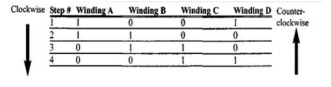
There are
several widely used sequences where each has a different degree of precision.
Table 5.4 shows a 2-phase, 4-step stepping sequence.
It must
be noted that although we can start with any of the sequences in Table 5.5,
once we start we must continue in the proper order. For example, if we start
with step 3 (0110), we must continue in the sequence of steps 4, 1,2, etc.
Step angle
Table 5.5 Stepper Motor Step Angle
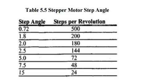
How much
movement is associated with a single step? This depends on the internal
construction of the motor, in particular the number of teeth on the stator and
the rotor. The step angle is the minimum degree of rotation associated with a
single step. Various motors have different step angles. Table 5.5 shows some
step angles for various motors. In Table 5.5, notice the term steps per
revolution. This is the total number of steps needed to rotate one complete
rotation or 360 degrees (e.g., 180 steps x 2 degrees = 360). It must be noted
that perhaps contrary to one's initial impression, a stepper motor does not
need more terminal leads for the stator to achieve smaller steps. All the
stepper motors discussed in this section have 4 leads for the stator winding
and 2 COM wires for the center tap. Although some manufacturers set aside only
one lead for the common signal instead of two, they always have 4 leads for the
stators. Next we discuss some associated terminology in order to understand the
stepper motor further.
Example 5.1
Describe
the 8051 connection to the stepper motor of Figure 5.11 and code a program to
rotate it continuously.
Solution:
The
following steps show the 8051 connection to the stepper motor and its
programming.
Use an ohmmeter to measure the
resistance of the leads. This should identify which COM leads are connected to
which winding leads.
The common wire(s) are connected
to the positive side of the motor's power supply.
In many
motors, +5 V is sufficient.
The four leads of the stator
winding are controlled by four bits of the 8051 port (Pl.O - P1.3). However,
since the 8051 lacks sufficient current to drive the stepper motor windings, we
must use a driver such as the ULN2003 to energize the stator. Instead of the
ULN2003, we could have used transistors as drivers, as shown in Figure 17-9.
However,
notice that if transistors are used as drivers, we must also use diodes to take
care of inductive current generated when the coil is turned off. One reason
that using the ULN2003 is preferable to the use of transistors as drivers is
that the ULN2003 has an internal diode to take care of back EMF.
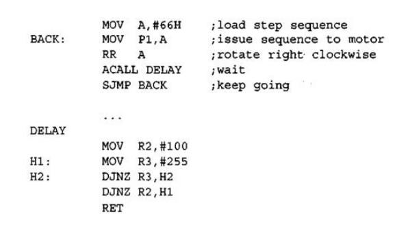
Change
the value of DELAY to set the speed of rotation. We can use the single-bit
instructions SETB and CLR instead of RR A to create the sequences.
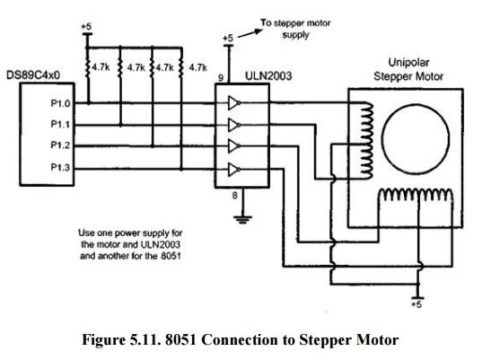
Figure 5.11. 8051 Connection to
Stepper Motor
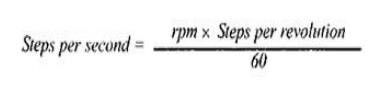
Steps per second and rpm relation:
The
relation between rpm (revolutions per minute), steps per revolution, and steps
per second is as follows.
The four-step sequence and number of teeth on rotor
The
switching sequence shown earlier in Table 5.4 is called the 4-step switching
sequence since after four steps the same two windings will be "ON"
How much movement is associated with these four steps? After completing every
four steps, the rotor moves only one tooth pitch. Therefore, in a stepper motor
with 200 steps per revolution, the rotor has 50 teeth since 4x50 = 200 steps
are needed to complete one revolution. This leads to the conclusion that the
minimum step angle is always a function of the number of teeth on the rotor. In
other words, the smaller the step angle, the more teeth the rotor passes.
Related Topics