Chapter: Mechanical and Electrical : Thermal Engineering : Steam Nozzles and Turbines
Steam Turbines
SIGNIFICANCE OF STEAM TURBINES
Ø Large scale electrical energy production largely depends on the use of turbines. Nearly all of the world's power that is supplied to a major grid is produced by turbines.
Ø From steam turbines used at coal-burning electricity plants to liquid water turbines used at hydro-electric plants, turbines are versatile and can be used in a number of applications.
Ø There are also gas turbines that combust natural gas or diesel fuel for use in remote locations or where a large backup power supply is required. Most power plants use turbines to produce energy by burning coal or natural gas.
Ø The heat produced from combustion is used to heat water in boiler. The liquid water is converted to steam upon heating and is exhausted through a pipe which feeds the steam to the turbine.
Ø The pressurized steam flow imparts energy on the blades and shaft of the turbine causing it to rotate.
Ø The rotational mechanical energy is then converted to electrical energy using a generator.
STEAM TURBINES
Turbines
Ø We shall consider steam as the working fluid
Ø Single stage or Multistage
Ø Axial or Radial turbines
Ø Atmospheric discharge or discharge below atmosphere in condenser
Ø Impulse/and Reaction turbine
Impulse Turbines
Ø Impulse turbines (single-rotor or multirotor) are simple stages of the turbines.
Ø Here the impulse blades are attached to the shaft.
Ø Impulse blades can be recognized by their shape.
Ø The impulse blades are short and have constant cross sections.
Schematic diagram of an Impulse Trubine
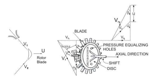
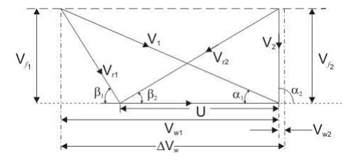
V1 and V2 = Inlet and outlet absolute velocity
Vr1 and V r2 = Inlet and outlet relative velocity (Velocity relative to the rotor blades.)
U = mean blade speed
= nozzle angle,
= absolute fluid angle at outlet
It is to be mentioned that all angles are with respect to the tangential velocity ( in the direction of U )
Velocity diagram of an Impulse Turbine
The Single-Stage Impulse Turbine
Ø The single-stage impulse turbine is also called the de Laval turbine after its inventor.
Ø The turbine consists of a single rotor to which impulse blades are attached.
Ø The steam is fed through one or several convergent-divergent nozzles which do not extend completely around the circumference of the rotor, so that only part of the blades is impinged upon by the steam at any one time.
Ø The nozzles also allow governing of the turbine by shutting off one or more them.
Compounding in Impulse Turbine
Ø If high velocity of steam is allowed to flow through one row of moving blades, it produces a rotor speed of about 30000 rpm which is too high for practical use.
Ø It is essential to incorporate some improvements for practical use and also to achieve high performance.
Ø This is called compounding.
Ø Two types of compounding can be accomplished: (a) velocity compounding and (b) pressure compounding
The Velocity - Compounding of the Impulse Turbine
Ø The velocity-compounded impulse turbine was first proposed to solve the problems of a single-stage impulse turbine for use with high pressure and temperature steam.
Ø It is composed of one stage of nozzles as the single-stage turbine, followed by two rows of moving blades instead of one.
Ø These two rows are separated by one row of fixed blades attached to the turbine stator, which has the function of redirecting the steam leaving the first row of moving blades to the second row of moving blades.
Pressure Compounding or Rateau Staging
Ø To alleviate the problem of high blade velocity in the single-stage impulse turbine, the total enthalpy drop through the nozzles of that turbine are simply divided up, essentially in an equal manner, among many single-stage impulse turbines in series,Such a turbine is called a Rateau turbine.
Ø The inlet steam velocities to each stage are essentially equal and due to a reduced Δh.
Reaction Turbine
Ø A reaction turbine, therefore, is one that is constructed of rows of fixed and rows of moving blades.
Ø The fixed blades act as nozzles.
Ø The moving blades move as a result of the impulse of steam received (caused by change in momentum) and also as a result of expansion and acceleration of the steam relative to them.
Ø The pressure drops will not be equal.
Ø They are greater for the fixed blades and greater for the high-pressure than the low-pressure stages.
Ø The absolute steam velocity changes within each stage as shown and repeats from stage to stage.
APPLICATIONS
Ø Locomotives
Ø Power generations
Ø Industrial application for producing steam
Governing of Steam Turbine: The method of maintaining the turbine speed constant irrespective of the load is known as governing of turbines. The device used for governing of turbines is called Governor. There are 3 types of governors in steam turbine,
1. Throttle governing
2. Nozzle governing
3. By-pass governing
i.Throttle Governing:
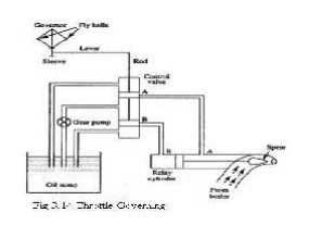
Let us consider an instant when the load on the turbine increases, as a result the speed of the turbine decreases. The fly balls of the governor will come down. The fly balls bring down the sleeve. The downward movement of the sleeve will raise the control valve rod. The mouth of the pipe AA will open. Now the oil under pressure will rush from the control valve to right side of piston in the rely cylinder through the pipe AA. This will move the piston and spear towards the left which will open more area of nozzle. As a result steam flow rate into the turbine increases, which in turn brings the speed of the turbine to the normal range.
ii)Nozzle Governing:
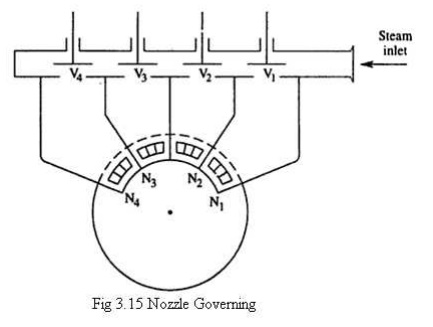
A dynamic arrangement of nozzle control governing is shown in fig.
In this nozzles are grouped in 3 to 5 or more groups and each group of nozzle is supplied steam controlled by valves. The arc of admission is limited to 180º or less. The nozzle controlled governing is restricted to the first stage of the turbine, the nozzle area in other stages remaining constant. It is suitable for the simple turbine and for larger units which have an impulse stage followed by an impulse reaction turbine.
Related Topics