Chapter: Solid State Drives : Drive Characteristics
Steady State Stability
Steady State Stability:
Equilibrium speed of motor-load system can be obtained when motor torque equals the load torque. Electric drive system will operate in steady state at this speed, provided it is the speed of stable state equilibrium.
Concept of steady state stability has been developed to readily evaluate the stability of an equilibrium point from the steady state speed torque curves of the motor and load system. In most of the electrical drives, the electrical time constant of the motor is negligible compared with the mechanical time constant. During transient condition, electrical motor can be assumed to be in electrical equilibrium implying that steady state speed torque curves are also applicable to the transient state operation.
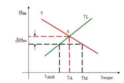
Now, consider the steady state equilibrium point A shown in figure below
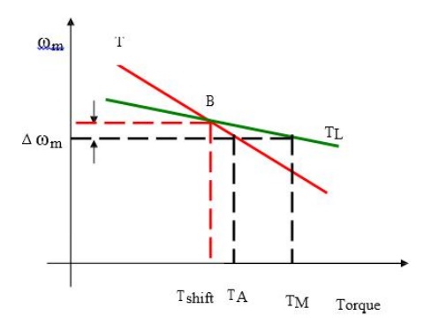
Now consider equilibrium point B which is obtained when the same motor drives another load as shown in the figure.
A decrease in speed causes the load torque to become greater than the motor torque, electric drive decelerates and operating point moves away from point B.
Similarly when working at point B and increase in speed will make motor torque greater than the load torque, which will move the operating point away from point B
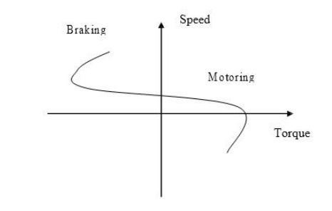
Basics of Regenerative Braking
In the regenerative braking operation, the motor operates as generator, while it is still connected to the supply. Here, the motor speed is greater than the synchronous speed.
Mechanical energy is converted into electrical energy, part of which is returned to the supply and rest of the energy is last as heat in the winding and bearings of electrical machines pass smoothly from motoring region to generating region, when over driven by the load.
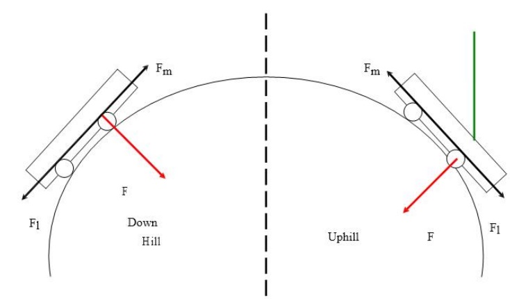
An example of regenerative braking is shown in the figure below. Here an electric motor is driving a trolley bus in the uphill and downhill direction. The gravity force can be resolved into two components in the uphill direction.
One is perpendicular to the load surface (F) and another one is parallel to the road surface Fl. The parallel force pulls the motor towards bottom of the hill.
If we neglect the rotational losses, the motor must produce force Fm opposite to Fl to move the bus in the uphill direction.
Here the motor is still in the same direction on both sides of the hill. This is known as regenerative braking. The energy is exchange under regenerative braking operation is power flows from mechanical load to source.
This operation is indicated as shown in the figure below in the first quadrant. Here the power flow is from the motor to load.
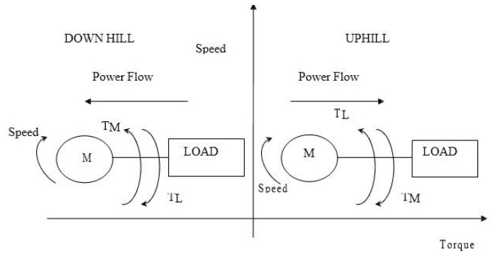
Now we consider that the same bus is traveling in down hill, the gravitational force doesn’t change its direction but the load torque pushes the motor towards the bottom of the hill. The motor produces a torque in the reverse direction because the direction of the motor torque is always opposite to the direction of the load torque.
Here the motor is still in the same direction on both sides of the hill. This is known as regenerative braking. The energy is exchange under regenerative braking operation is power flows from mechanical load to source. Hence, the load is driving the machine and the machine is generating electric power that is returned to the supply.
Regenerative braking of Induction motor:
An induction motor is subjected to regenerative braking, if the motor rotates in the same direction as that of the stator magnetic field, but with a speed greater than the synchronous speed. Such a state occurs during any one of the following process.
ü Downward motion of a loaded hoisting mechanism
ü During flux weakening mode of operation of IM.
Under regenerative braking mode, the machine acts as an induction generator. The induction generator generates electric power and this power is fed back to the supply. This machine takes only the reactive power for excitation.
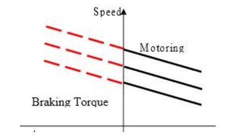
The speed torque characteristic of the motor for regenerative braking is shown in the figure.
Regenerative Braking for DC motor:
In regenerative braking of dc motor, generated energy is supplied to the source. For this the following condition is to be satisfied.
E > V and Ia should be negative
Modes of Operation:
An electrical drive operates in three modes
ü Steady state
ü Acceleration including Starting
ü Deceleration including Stopping
We know that
T=T1 +J d/dt (ωm)
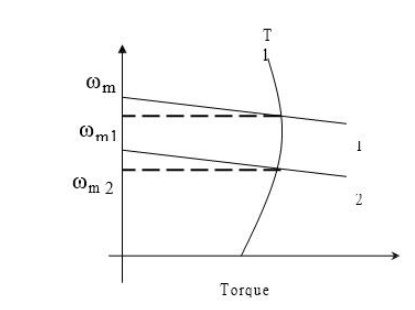
According to the above expression the steady state operation takes place when motor torque equals the load torque. The steady state operation for a given speed is realized by adjustment of steady state motor speed torque curve such that the motor and load torques are equal at this speed. Change in speed is achieved by varying the steady state motor speed torque curve so that motor torque equals the load torque at the new desired speed. In the figure shown below when the motor parameters are adjusted to provide speed torque curve 1, drive runs at the desired speedωm 1 .
Speed is changed to ωm 2 when the motor parameters are adjusted to provide speed torque curve
2. When load torque opposes motion, the motor works as a motor operating in quadrant I or III depending on the direction of rotation. When the load is active it can reverse its sign and act to assist the motion. Steady state operation for such a case can be obtained by adding a mechanical brake which will produce a torque in a direction to oppose the motion. The steady state operation is obtained at a speed for which braking torque equal the load torque. Drive operates in quadrant II or IV depending upon the rotation.
Acceleration and Deceleration modes are transient modes. Drive operates in acceleration mode whenever an increase in its speed is required. For this motor speed torque curve must be changed so that motor torque exceeds the load torque. Time taken for a given change in speed depends on inertia of motor load system and the amount by which motor torque exceeds the load torque.
Increase in motor torque is accompanied by an increase in motor current. Care must be taken to restrict the motor current with in a value which is safe for both motor and power modulator. In applications involving acceleration periods of long duration, current must not be allowed to exceed the rated value. When acceleration periods are of short duration a current higher than the rated value is allowed during acceleration.
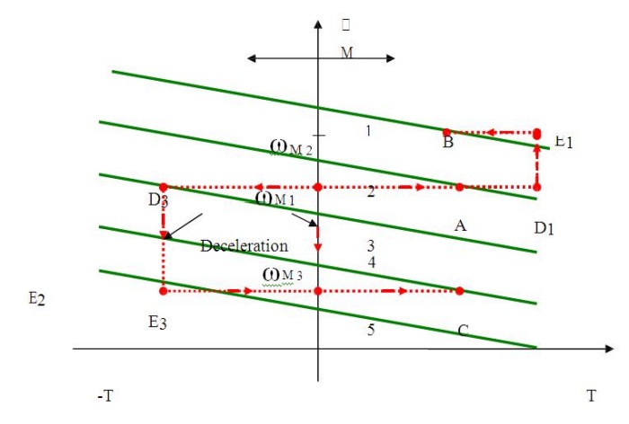
In closed loop drives requiring fast response, motor current may be intentionally forced to the maximum value in order to achieve high acceleration. Figure shown below shows the transition from operating point A at speed.
Point B at a higher speedωm 2, when the motor torque is held constant during acceleration. The path consists of AD1E1B. In the figure below, 1 to 5 are motor speed torque curves. Starting is a special case of acceleration where a speed change from 0 to a desired speed takes place. All points mentioned in relation to acceleration are applicable to starting.
The maximum current allowed should not only be safe for motor and power modulator but drop in source voltage caused due to it should also be in acceptable limits. In some applications the motor should accelerate smoothly, without any jerk. This is achieved when the starting torque can be increased step lessly from its zero value. Such a start is known as soft start.
Related Topics