Chapter: Power System Operation and Control : Reactive Power -Voltage Control
Static VAR Compensators
STATIC VAR COMPENSATORS
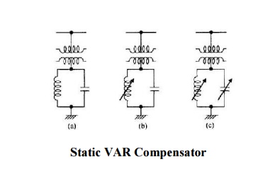
Ø The term static var compensator is applied to a
number of static var compensation devices for use in shunt reactive control.
Ø These devices consist of shunt connected,
static reactive element (linear or non linear reactors and capacitors)
configured into a var compensating system.
Ø Some possible configurations are shown in above
Figure.
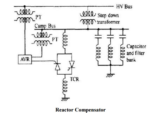
Ø Even though the capacitors and reactors in are
shown in figure connected to the low voltage side of a down transformer, the
capacitor banks may be distributed between high and low voltage buses.
Ø The capacitor bank often includes, in part,
harmonic filters which prevent the harmonic currents from flowing in the
transformer and the high voltage system.
Ø Filters for the 5th and 7th harmonics are
generally provided.
Ø The thyristor controlled reactor (TCR) is
operated on the low voltage bus.
Ø In another form of the compensator illustrated
in Figure the reactor compensator is connected to the secondary of a
transformer.
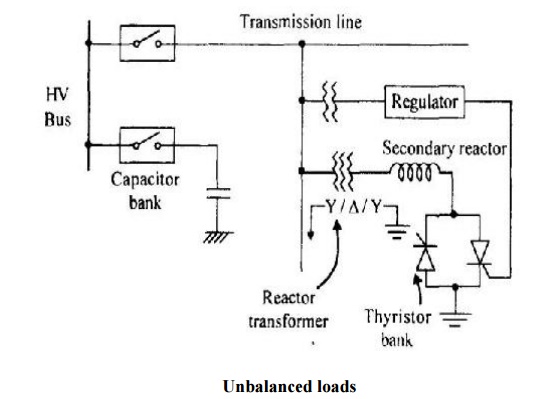
Ø With this transformer, the reactive power can
be adjusted to anywhere between 10% to the rated value.
Ø With a capacitor bank provided with steps, a
full control range from capacitive to inductive power can be obtained.
Ø The reactor's transformer is directly connected
to the line, so that no circuit breaker is needed.
Ø The primary winding is star connected with
neutral grounded, suitable to the thyristor network.
Ø The secondary reactor is normally nonexistent,
as it is more economical to design the reactor transformer with 200% leakage
impedance between primary and secondary windings.
Ø The delta connected tertiary winding will
effectively compensate the triple harmonics.
Ø The capacitor bank is normally subdivided and
connected to the substation bus bar via one circuit breaker per sub bank.
Ø The regulator generates firing pulses for the
thyristor network in such a way that the reactive power required to meet the
control objective at the primary side of the compensator is obtained.
Ø The reactor transformer has a practically
linear characteristic from no load to full load condition.
Thus, even under all stained over voltages;
hardly any harmonic content is generated due to saturation.
Ø The
transformer core has non ferromagnetic .Gaps to the required linearity.
The following requirements are to be borne in
mind while designing a compensator.
1. Reaction should be possible, fast or slow,
whenever demanded. No switching of capacitor should take place at that time to
avoid additional transients in the system. Commutation from capacitor to
reactor and vice versa should be fast.
2. No switching of the capacitors at the high
voltage bus bar, so that no higher frequency Transients is produced at EHV
level.
3. Elimination of higher harmonics on the
secondary side and blocking them from entering the system.
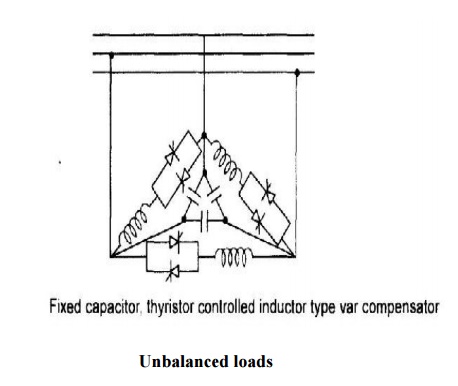
In a three phase system the thyristor controlled inductors are
normally delta connected as shown in Figure to compensate unbalanced loads and
the capacitors may be star or delta connected
Ø In the thyristor controlled reactor, the
inductive reactance is controlled by the thyristors.
Ø For a limited range of operation the
relationship between the inductive current iL and the
applied voltage V is represented in Figure. As the inductance is varied, the
susceptance varies over a range within the limits BLmin and BLmax
(corresponding to XLmax and XLmin) while the voltage
Changes by v volts.
Ø The current flowing in the inductance would be
different in each half cycle, varying with the conduction angle such that each
successive half cycle is a smaller segment of a sine wave.
Ø The fundamental component of inductor current
is then reduced to each case.
Ø Quick control can be exercised within one half
cycles, just by giving a proper step input to the firing angle control Static
var compensators when installed reduce the voltage swings at the rolling mill
and power system buses in drive system applications.
Ø They compensate for the average reactive power
requirements and improve power factor.
Ø Electric arc furnaces impose extremely
difficult service requirements on electrical power systems since the changes in
arc furnace load impedance are rapid.
Ø Random and non symmetrical.
Ø The three phases of a static var compensator
can be located independently so that it compensates for the unbalanced reactive
load of the furnace and the thyristor controller will respond quickly in order
to minimize the voltage fluctuations or voltage flicker seen by the system.
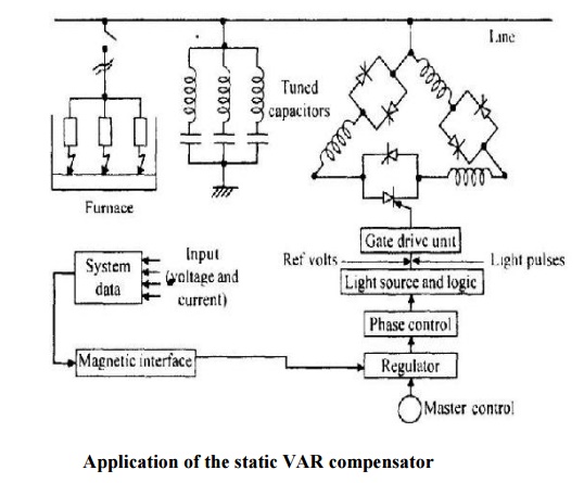
Ø Thus, the furnace characteristics are made more
acceptable to the power system by the static var compensator.
Ø Above figure shows the application of the
static var compensator to an arc furnace installation for reactive power compensation
at the HV bus level.
Related Topics