Chapter: Civil : Mechanics Of Solids : Transverse Loading On Beams And Stresses In Beam
Spring Deflection and Wahl's Factor
SPRING DEFLECTION
Spring
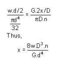
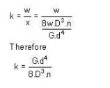
striffness: The stiffness is
defined as the load per unit deflection therefore
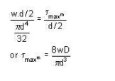
Shear stress
WAHL'S FACTOR :
In order to take into account
the effect of direct shear and change in coil curvature a stress factor is
defined, which is known as Wahl's factor.
K = Wahl' s factor and is
defined as
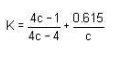
Where C = spring index
= D/d
if we take into
account the Wahl's
factor than the
formula for the
shear stress
becomes
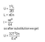
Strain Energy : The strain energy is defined as the energy
which is stored within a material when the work has been done on the
material.
In the case of a spring the
strain energy would be due to bending and the strain energy due to bending is
given by the expansion
Deflection of
helical coil springs under axial loads
Deflection of springs
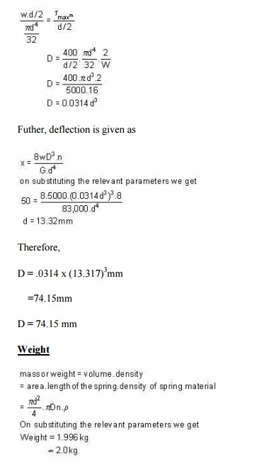
Example: A close coiled helical spring is to carry a
load of 5000N with a deflection of 50 mm and a maximum shearing stress
of 400 N/mm2 .if the number of active turns or active coils is
8.Estimate the following:
(i) wire diameter
(ii) mean coil diameter
(iii) weight of the spring.
Assume G = 83,000 N/mm2 ; = 7700 kg/m3
solution :
(i)
for wire
diametre if W is the axial load, then
Design of helical coil
springs
Helical spring design
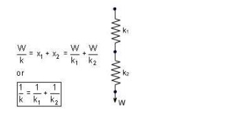
Springs in Series: If two springs of different stiffness are
joined endon and carry a common load W, they are said to be connected in
series and the combined stiffness and deflection are given by the following
equation.
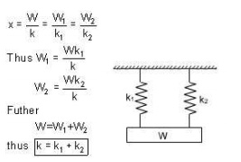
Springs in
parallel: If the two spring are joined
in such a way that they have a common deflection 'x' ; then they are said to be connected in
parallel.In this care the load carried is shared
between the two springs and total load W = W1
+ W2
stresses in helical coil
springs under torsion loads
Stresses under torsion
Shear Stress in the Shaft
When a shaft is subjected to
a torque or twisting, a shearing stress is produced in the shaft. The shear
stress varies from zero in the axis to a maximum at the outside surface of the
shaft.
The shear stress in a solid circular shaft in
a given position can be expressed as:
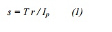
where
s = shear stress (MPa, psi)
T = twisting moment (Nmm, in lb)
r = distance from center to stressed surface
in the given position (mm, in)
Ip =
"polar moment of inertia" of cross section (mm4, in4)
The "polar
moment of inertia" is a measure of an object's ability to resist torsion.
Circular Shaft
and Maximum Moment
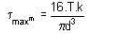
Maximum moment in a circular shaft can be
expressed as:
Tmax = smax Ip / R (2)
where
Tmax =
maximum twisting moment (Nmm, in lb)
smax =
maximum shear stress (MPa, psi)
R = radius of shaft
(mm, in)
Combining (2) and (3) for a solid
shaft
|
Tmax
= (p/16) smax D3 |
(2b) |
Combining (2) and (3b) for a hollow
shaft
|
Tmax
= (p/16) smax (D4 - d4) / D |
(2c) |
Circular Shaft
and Polar Moment of Inertia
Polar moment of inertia of a
circular solid shaft can be expressed as
|
Ip =
p R4/2 = p D4/32 |
(3) |
where
D = shaft outside
diameter (mm, in)
Polar moment of inertia of a
circular hollow shaft can be expressed as
Ip = p
(D4 - d4) /32 (3b)
where
d = shaft inside
diameter (mm,
in)
Diameter of a Solid
Shaft
Diameter of a solid shaft can
calculated by the formula
|
D = 1.72 (Tmax/smax)1/3 |
(4) |
Torsional
Deflection of Shaft
The angular deflection of a
torsion shaft can be expressed as
= L T / Ip G (5)
where
? = angular shaft
deflection (radians)
L = length of
shaft (mm, in)
G = modulus of
rigidity (Mpa, psi)
The angular deflection of a
torsion solid shaft can be expressed as
|
? = 32 L T / (G
p D4) |
(5a) |
The angular deflection of a
torsion hollow shaft can be expressed as
? = 32 L T / (G p
(D4- d4))
The angle in degrees can be
achieved by multiplying the angle ? in radians with 180/p
Solid shaft (p replaced)
?degrees � 584 L T / (G D4) (6a)
Hollow shaft (p replaced)
?degrees � 584 L T / (G (D4- d4) (6b)
Related Topics