Chapter: Mechanical : Design of Machine Elements : Design of Bearings Miscellaneous Elements
Solved Problems: Design of Bearings Miscellaneous Elements
Design a
journal bearing for a centrifugal pump from the following data: load on the
journal 2000N; speed of the journal=900r.p.m; Type of oil is SAE 10, for which
absolute viscosity at 550C=0.017KG/M-S ambient temperature of oil =15.50°C;
maximum bearing pressure of the pump=1.5 N/mm2. Calculate also mass
of the lubricating oil required for artificial cooling, if rise of temperature
of oil be limited to 10°C. heat dissipation co- efficient=1232 W/m2/°C.
Given :
W = 20000 N ;
N = 900
r.p.m. ;
to = 55°C
;
Z = 0.017
kg/m-s ;
ta = 15.5°C
;
=
1.5 N/mm2 ;
=
10°C ;
C = 1232
W/m2/°C
The journal bearing is designed as discussed in the following steps:
First of
all, let us find the length of the journal (l). Assume the diameter of the journal
(d) as 100mm. From Table 26.3, we find that the ratio of l / d for centrifugal
pumps varies from 1 to 2. Let us take l / d = 1.6.
l = 1.6 d = 1.6 × 100 = 160 mm
2. We know
that bearing pressure,
Since the
given bearing pressure for the pump is 1.5 N/mm2, therefore the above value of
p is safe and hence the dimensions of l and d are safe.

= 12.24
From
Table 26.3, we find that the operating value of (Z N/p) = 28
The
minimum value of the bearing modulus at which the oil film will break is given
by

Bearing
modulus at the minimum point of friction,
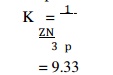
Since the
calculated value of bearing characteristic number is more than 9.33, therefore
the bearing will operate under hydrodynamic conditions.
From
Table 26.3, we find that for centrifugal pumps, the clearance ratio (c/d)
=0.0013
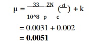
We know
that coefficient of friction,
6. Heat generated,
Qg = µ WV
= µ
W(πDN/60)
= 480.7 W
7. Heat
dissipated,
Qd = C.A (tb – ta)
= C.l.d
(tb – ta) W
We know
that
(tb – ta)
= ½ (t0 – ta) .
½ (55°–
15.5°)
19.75°C
Qd = 1232
× 0.16 × 0.1 × 19.75
= 389.3 W
We see
that the heat generated is greater than the heat dissipated which indicates
that the bearing is warming up. Therefore, either the bearing should be
redesigned by taking t0 = 63°C or the bearing should be cooled artificially.
We know
that
The
amount of artificial cooling required =
Heat generated – Heat dissipated
= Qg – Qd
= 480.7 –
389.3
=
91.4 W
Mass of lubricating oil required for artificial cooling
Let m = Mass of the lubricating oil required for artificial
cooling in kg / s. We know that the heat taken away by the oil,
Qt = m.S.t = m × 1900 × 10 = 19 000 m W Equating
this to the amount of artificial cooling required, we have
19000 m =
91.4
= 91.4 / 19 000
=0.0048 kg / s
=0.288 kg / min
A 150 mm diameter shaft supporting a load of 10 kN has a speed of 1500 r.p.m. The shaft runs in a bearing whose length is 1.5 times the shaft diameter. If the diametral clearance of the bearing is 0.15 mm and the absolute viscosity of the oil at the operating temperature is 0.011 kg/m-s, find the power wasted in friction
Solution.
Given :
d = 150
mm = 0.15 m W = 10 kN = 10000 N N = 1500 r.p.m.
= 1.5 d
c = 0.15 mm
Z = 0.011 kg/m-s We know that length of bearing,
= 1.5 d
=1.5 × 150
=225 mm
Bearing pressure,
= W / A
=W / ld
=10000 / (225 x150)
=0.296 N/mm
We know
that coefficient of friction,
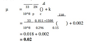
=0.018 + 0.002
=0.02
Rubbing
velocity, V = πdN/60
=π x 0.15 x 1500 / 60
=11.78 m/ s
We know that heat generated due to friction, Qg = µ.W.V
=0.02 ×
10 000 × 11.78
=2356 W
Power
wasted in friction
Qg= 2356 W
= 2.356 kW
A footstep
bearing supports a shaft of 150 mm diameter which is counterbored at the end
with a hole diameter of 50 mm. If the bearing pressure is limited to 0.8 N/mm2
and the speed is 100 r.p.m.; find : 1. The load to be supported; 2. The power
lost in friction; and 3. The heat generated at the bearing.
Assume
coefficient of friction = 0.015. Solution.
Given :
D = 150
mm R = 75 mm d = 50 mm r = 25 mm
p = 0.8
N/mm2 N = 100 r.p.m.
= 0.015
Load
to be supported
Let W =
Load to be supported.
Assuming
that the pressure is uniformly distributed over the bearing surface, therefore
bearing pressure (p),
= W / π(R2 – r2)
=W / π(752 – 252) W = 0.8 ×
15710
= 12568 N
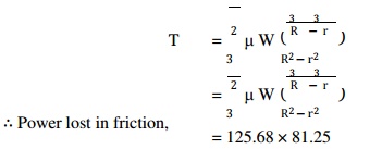
=125.68 × 81.25
=10212 N-mm = 10.212 N-m
=P= 2 πNT
/ 60
=2π x 100 x 10.212 / 60
=107 W = 0.107 kW
Heat generated
at the bearing
We know
that heat generated at the bearing =
Power lost in friction
=0.107 kW or kJ / s
=0.107 × 60
= 6.42
kJ/min
Design a
self-aligning ball bearing for a radial load of 7000 N and a thrust load of
2100 N. The desired life of the bearing is 160 millions of revolutions at 300
r.p.m. Assume uniform and steady load,
Solution.
Given :
WR = 7000
N WA = 2100 N
L = 160 ×
106 rev N = 300 r.p.m.
From
Table 27.4, we find that for a self-aligning ball bearing, the values of radial
factor (X )
and thrust
factor (Y) for WA / WR = 2100 / 7000 = 0.3, are as follows : X = 0.65 and Y =
3.5
Since the
rotational factor (V ) for most of the bearings is 1, therefore dynamic
equivalent load,
= X.V.WR + Y.WA
=0.65 × 1 × 7000 + 3.5 × 2100
=11900 N
From
Table 27.5, we find that for uniform and steady load, the service factor KS for
ball bearingsis 1. Therefore the bearing should be selected for W = 11900 N. We
know that the basic dynamic load rating,
= 11900
=
64600 N = 64.6 kN
From
Table 27.6, let us select bearing number 219 having C = 65.5
kN
A single
row angular contact ball bearing number 310 is used for an axial flow
compressor. The bearing is to carry a radial load of 2500 N and an axial or
thrust load of 1500 N. Assuming light shock load, determine the rating life of
the bearing.
Solution.
Given :
WR = 2500
N
WA = 1500
N
From Table
27.4, we find that for single row angular contact ball bearing, the values of
radial factor (X) and thrust factor (Y ) for WA / WR = 1500 / 2500 = 0.6 are
X = 1 and
Y = 0
Since the
rotational factor (V) for most of the bearings is 1, therefore dynamic
equivalent load,
= X.V.WR + Y.WA
=1 × 1 × 2500 + 0 × 1500
=2500 N
From
Table 27.5, we find that for light shock load, the service factor (KS) is 1.5.
Therefore the design dynamic equivalent load should be taken as
= 2500 × 1.5
=
3750 N
From Table
27.6, we find that for a single row angular contact ball bearing number 310,
the basic dynamic capacity,
= 53 kN
=
53000 N
We know
that rating life of the bearing in revolutions,
= (C/W)k x 106
=(53000/3750)3 x 106
=2823 × 106 rev
The thrust
of propeller shaft in a marine engine is taken up by a number of collars
integral with the shaft which is 300 mm is diameter. The thrust on the shaft is
200 kN and the speed is 75 r.p.m. Taking µ constant
and equal to 0.05 and assuming the bearing pressure as uniform and equal to 0.3
N/mm2, find : 1. Number of collars required, 2.Power lost in friction, and 3.
Heat generated at the bearing in kJ/min.
Solution.
Given :
d = 300
mm r = 150 mm ;
W = 200
kN = 200 × 103 N ; N = 75 r.p.m. ;
= 0.05 ;
p = 0.3
N/mm2
1. Number
of collars required
Let n =
Number of collars required.
Since the outer diameter of the collar (D) is taken
as 1.4 to 1.8 times the diameter of shaft (d ), therefore
let us
take
= 1.4 d
=1.4 × 300
=420 mm
R = 210 mm
We know
that the bearing pressure ( p), 0.3 = W / nπ(R2 – r2)
=200 x 103 / nπ(2102 1502) n = 2.947 / 0.3
=9.8 say 10
Power lost
in friction
We know
that total frictional torque,
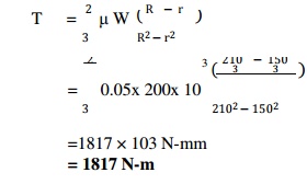
=1817 ×
103 N-mm
=
1817 N-m
Power
lost in friction,
= 2 πN T / 60
=2 π x 75 x 1817 / 60
=14270 W
=14.27 kW
3. Heat
generated at the bearing
We know
that heat generated at the bearing
Power lost in friction
=14.27 kW or kJ/s
=14.27 × 60
=856.2 kJ/min
A wall
bracket supports a plummer block for 80 mm diameter shaft. The length of
bearing is 120 mm. The cap of bearing is fastened by means of four bolts, two
on each side of the shaft. The cap is to withstand a load of 16.5 kN. The
distance between the centre lines of the bolts is A self-locking nut used in
bearing assemblies. 150 mm. Determine the thickness of the bearing cap and the
diameter of the bolts. Assume safe stresses in tension for the material of the
cap, which is cast iron, as 15 MPa and for bolts as 35 MPa. Also check the deflection
of the bearing cap taking E = 110 kN / mm2.
Solution
:
Given :
d = 80 mm
; l = 120 mm ; n = 4 ;
W = 16.5
kN = 16.5 × 10³ N ; a = 150 mm ;
σb = 15
MPa = 15 N/mm2; σt = 35 MPa = 35 N/mm2 ;
E = 110
kN/mm2 = 110 × 103 N/mm2
Thickness
of the bearing cap
We know
that thickness of the bearing cap,
t = 45.4 say 46 mm
Diameter
of the bolts
Let dc =
Core diameter of the bolts. We know that
(π/ 4 )× (dc)2 σt = (4/3) (W/n)
(π/ 4 )×
(dc)2 x 35 = (4/3) (16.5 x 10³/4)
dc = 14.2 mm
Deflection
of the cap
We know
that deflection of the cap,
= (Wa3 / 4Elt3)
=(16.5 x 103 x 1503) / (4 x
110 x 103 x 120 x 463)
=0.0108 mm
Since the
limited value of the deflection is 0.025 mm, therefore the above value of
deflection is within limits.
Related Topics