Chapter: Electrical Drives & Control : Conventional and Solid State Speed Control Of D.C Drives
Solid state Speed Control of DC Motor
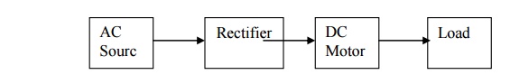
Solid state Speed Control of DC Motor:
The DC Motor speed can be controlled through power semiconductor switches. The power semiconductor switches are SCR, MOSFET, IGBT etc., this type of speed control is called static ward leonard Drive.
Types of DC Drives:
Phase controlled rectifier fed DC drives
Single phase rectifier fed DC drives
Three phase rectifier fed DC drives
One quadrant converter
Two quadrant converter
Four quadrant converter
Chopper fed DC drives
One quadrant Chopper drives
Two quadrant Chopper drives
Four quadrant Chopper drives
Single phase Controlled rectifier fed DC drives:
Half wave controlled rectifiers
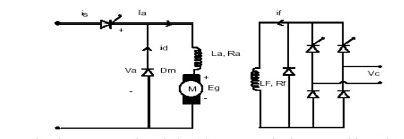
In the single phase half controlled rectifier, the load resister, RL is connected in series with anode A.
A variable resistance r is inserted in the gate circuit for controlling gate current. During the negative half cycles of the input ac voltage .
The SCR does not conduct regardless of the gate voltage, because anode is negative with respect to cathode K.
The SCR will conduct during the positive half cycles provided appropriate gate current is made to flow .the gate current can be varied with the help of variable resistance r inserted in the gate circuit for this purpose .the greater the gate current, the lesser will be the supply voltage at which SCR will start conducting.
Assume that the gate current is such that SCR starts conducting at a positive voltage V, being less than peak value of input ac voltage Vmax,
it is clear that the SCR starts conducting, as soon as input ac voltage becomes equal to V volts in the positive half cycle, and will continue conducting till ac voltage becomes zero when it will turn-off, again in next positive half cycle, SCR will start conducting when input ac voltage becomes equal to V volts.
The angle by which the SCR starts conducting is called as firing angle or delay angle a the conduction will take place for( P -a ) radians.
The thyristor circuit uses phase commutation.
The average output voltage (VL) from a half-wave controlled rectifier for the given input ac voltage V=Vmaxsin w t
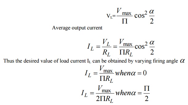
Hence, load current decreases with the increase in value of firing anglea . So the terminal voltage decreases the motor run slowly and vice versa.
With Freewheeling diode
Let RL load is connected with the single-phase half controlled rectifier .Due to the inductive nature of the load, the load current lags by an angle qwith respect to the voltage.
During voltage reversal, the voltage reaches zero but due to the inductive nature of the load, the current still flow through the thyristor.
it takes some time for the current to reach zero. so during that instant ,a negative voltage will be appearing across the inductive load and the freewheeling diode connected in parallel with the load is turned on, as the diode is turned on, the load voltage becomes the diode forward drop.
It is otherwise called commutating diode. This diode is connected anti parallel with load .this diode comes into picture only when the load is inductive.
In case of inductive load even though the input voltage reaches zero and becomes negative, the current is still flowing through the thyristor, so it remains on when the voltage across the load becomes negative.
The freewheeling diode is turned on when the load voltage is negative.
So, the voltage across the load becomes zero and it provides a path for the load current. During this interval, the energy stored in the inductor is dissipated through this diode
This freewheeling diode prevents the negative the negative reversal of voltage across the load.
It improves the input power factor.
It improves the load current wave from thereby it improves the performance parameters.
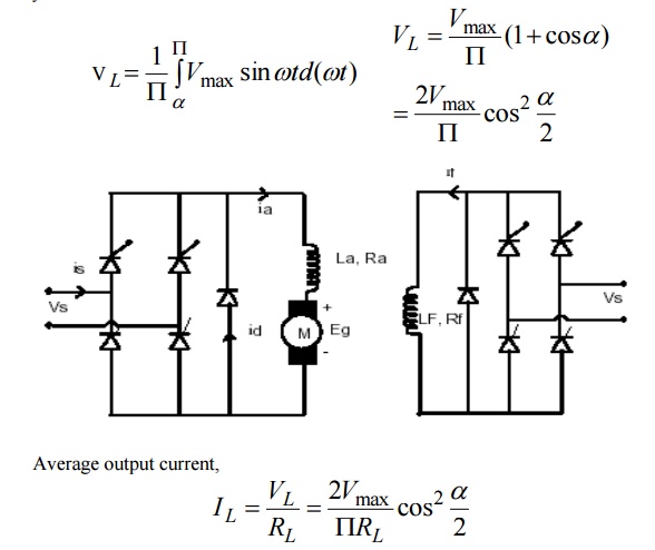
Full controlled rectifier
The full wave half controlled rectifier circuit consists of two thyristors and two diodes.
The gates of both thyristors are supplied from two gate control supply circuits.
One thyristors (or SCR) conducts during the positive half cycles and the other during the negative half cycles and thus unidirectional current flows through the load circuit.
Now, if the supply voltage v =Vmaxsin w t and firing angle is a ,then average output voltage is given by
Advantages:
Basic operation is simple and reliable
Time response is faster
Small size
Less weight
Disadvantages:
Introduce current and voltage harmonics into supply systems
The overload capacity is lower
Due to switching of SCR distortion of the AC supply voltage and telephone interference may be produced.
Chopper Fed DC Drives
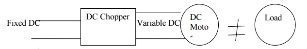
Fixed DC voltage is fed to the DC chopper circuit.
DC chopper converts fixed DC into variable DC voltage.
This variable DC Voltage is fed to the motor.
By varying the DC voltage, the motor speed can be controlled.
Self commutated devices such as MOSFET‟s, Power transistors, IGBT‟s and IGCT‟s are used for building choppers because they can be commutated by a low power control signal and do not need commutation circuit and can be operated at a higher frequency for the same rating.
Advantages:
High efficiency
Light weight
Flexibility in controls
Small size
Quick response
Applications:
Battery operated vehicles
Traction motors
Hoists
Electric braking
Trolley cars
Related Topics