Chapter: Measurements and Instrumentation : Electrical and Electronics Instruments
Single and Three Phase Wattmeters and Energy Meters: Construction and principle of operation
Single And Three Phase Wattmeters And Energy Meters
Single Phase Induction Type Meters
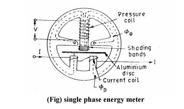
The construction and principle of operation of Single Phase Energy Meters is explained below
Construction of Induction Type Energy Meters
There are four main parts of the operating mechanism
(i) Driving system
(ii) Moving system
(iii) Braking system
(iv) Registering system
i. Driving system
The driving system of the meter consists of two electro-magnets.
The core of these electromagnets is made up of silicon steel laminations. The coil of one of the electromagnets is excited by the load current. This coil is called the current coil.
The coil of second electromagnet is connected across the supply and, therefore, carries a current proportional to the supply voltage. This coil is called the pressure coil.
Consequently the two electromagnets are known as series and shunt magnets respectively.
Copper shading bands are provided on the central limb. The position of these bands is adjustable.
The function of these bands is to bring the flux produced by the shunt magnet exactly in quadrature with the applied voltage.
ii. Moving System
This consists of an aluminum disc mounted on a light alloy shaft.
This disc is positioned in the air gap between series and shunt magnets. The upper bearing of the rotor (moving system) is a steel pin located in a hole in the bearing cap fixed to the top of the shaft.
The rotor runs on a hardened steel pivot, screwed to the foot of the shaft. The pivot is supported by a jewel bearing.
A pinion engages the shaft with the counting or registering mechanism.
iii. Braking System
A permanent magnet positioned near the edge of the aluminium disc forms the braking system. The aluminium disc moves in the field of this magnet and thus provides a braking torque.
The position of the permanent magnet is adjustable, and therefore braking torque can be adjusted by shifting the permanent magnet to different radial positions as explained earlier.
iv. Registering (counting) Mechanism
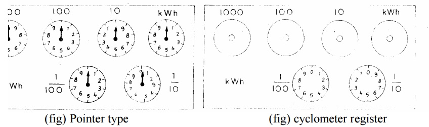
The function of a registering or counting mechanism is to record continuously a number which is proportional to the revolutions made by the moving system. By a suitable system, a train of reduction gears the pinion on the rotor shaft drives a series of five or six pointers.
These rotate on round dials which are marked with ten equal divisions.
The pointer type of register is shown in Fig. Cyclo-meter register as shown in Fig can also he used.
Errors in Single Phase Energy Meters
The errors caused by the driving system are
(i) Incorrect magnitude of fluxes.
(ii) Incorrect phase angles.
(iii) Lack of Symmetry in magnetic circuit.
The errors caused by the braking system are
i) changes in strength of brake magnet
ii) changes in disc resistance
iii) abnormal friction
iv) self braking effect
Three Phase General Supply with Controlled Load
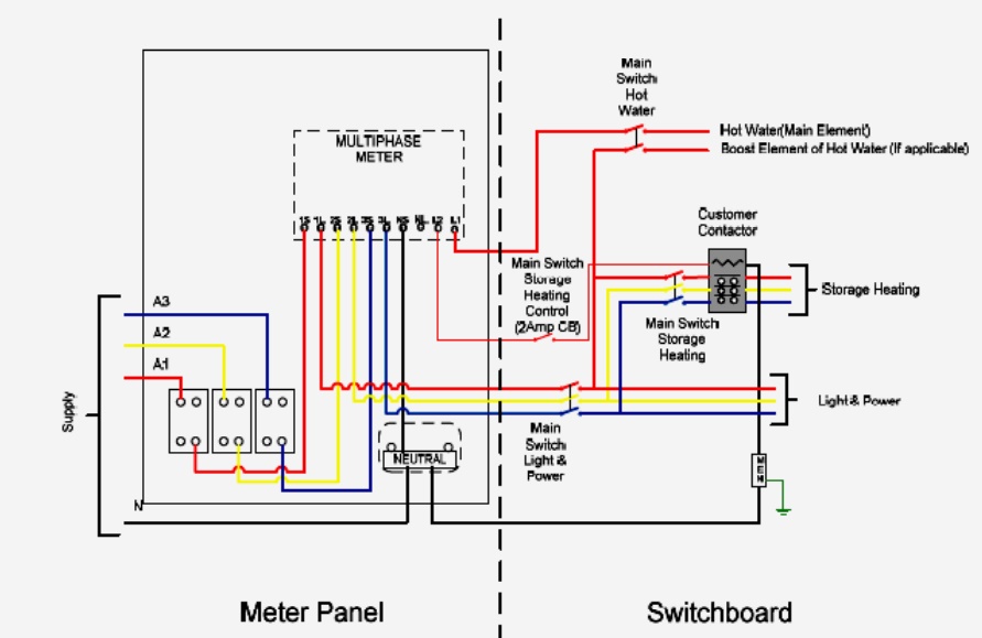
L1 – 30A Load Control (Hot Water)
L2 – Maximum 2A Load Control (Storage Heating)
2.5mm² with 7 strands for conductors to control customer contactor Load carrying conductors not less than 4mm² or greater than 35mm²
All metering neutrals to be black colour 4mm² or 6 mm² with minimum 7 stranded conductors.
Not less than 18 strand for 25 & 35mm² conductors
Refer to SIR’s for metering obligations
Comply with Electrical Safety (Installations) Regulations 2009 and AS/NZS 3000 Customer needs to provide 2A circuit breaker as a Main Switch and their load control contactor
Within customer’s switchboard
Meter panel fuse not required for an overhead supply.
Off Peak controlled load only includes single phase hot water & single or multi-phase storage heating
Wiring diagram applicable for Solar
Metering diagram is applicable for 2 or 3 phase load.
For 2 phase loads – Red and Blue phase is preferred.
WATTMETER
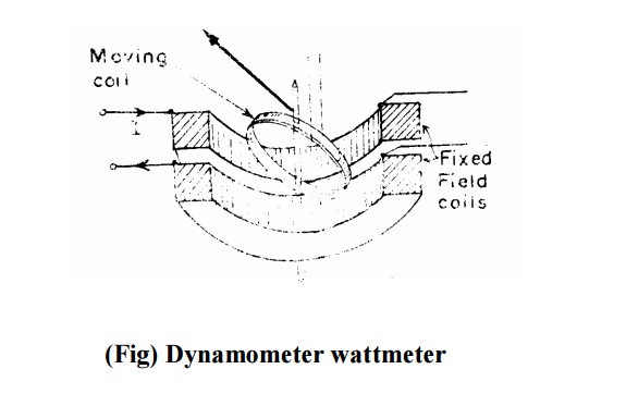
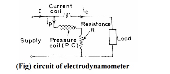
Electrodynamometer Wattmeters
These instruments are similar in design and construction to electrodynamometer type ammeters and voltmeters.
The two coils are connected in different circuits for measurement of power.
The fixed coils or “ field coils” arc connected in series with the load and so carry the current in the circuit.
The fixed coils, therefore, form the current coil or simply C.C. of the wattmeter.
The moving coil is connected across the voltage and, therefore, carries a current proportional to the voltage.
A high non-inductive resistance is connected in series with the moving coil to limit the current to a small value.
Since the moving coil carries a current proportional to the voltage, it is called the ‘ ‘ pressure coil’ ’ or “ voltage coil” or simply called P.C. of the wattmeter.
Construction of Electrodynamometer Wattmeter
Fixed Coils
The fixed coils carry the current of the circuit. They are divided into two halves.
The reason for using fixed coils as current coils is that they can be made more massive and can be easily constructed to carry considerable current since they present no problem of leading the current in or out.
The fixed coils are wound with heavy wire. This wire is stranded or laminated especially when carrying heavy currents in order to avoid eddy current losses in conductors. The fixed coils of earlier wattmeters were designed to carry a current of 100 A but modem designs usually limit the maximum current ranges of wattmeters to about 20 A. For power measurements involving large load currents, it is usually better to use a 5 A wattmeter in conjunction with a current transformer of suitable range.
Damping
Air friction damping is used.
The moving system carries a light aluminium vane which moves in a sector shaped box. Electromagnetic or eddy current damping is not used as introduction of a permanent magnet (for damping purposes) will greatly distort the weak operating magnetic field.
Scales and Pointers
They are equipped with mirror type scales and knife edge pointers to remove reading errors due to parallax.
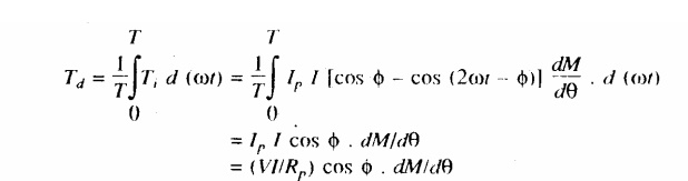
Theory of Electrodynamometer Watt-meters
It is clear from above that there is a component of power which varies as twice the frequency of current and voltage (mark the term containing 2 Ȧt).
Average deflecting torque
Controlling torque exerted by springs Tc= Kș
Where, K = spring constant; ș= final steady deflection.
Errors in electrodynamometer
i) Errors due to inductance effects
ii) Stray magnetic field errors
iii) Eddy current errors
iv) Temperature error
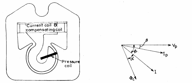
Ferrodynamic Wattmeters
The operating torque can be considerably increased by using iron cores for the coils.
Ferrodynamic wattmeters employ cores of low loss iron so that there is a large increase in the flux density and consequently an increase in operating torque with little loss in accuracy.
The fixed coil is wound on a laminated core having pole pieces designed to give a uniform radial field throughout the air gap.
The moving coil is asymmetrically pivoted and is placed over a hook shaped pole piece.
This type of construction permits the use of a long scale up to about 270° and gives a deflecting torque which is almost proportional to the average power. With this construction there is a tendency on the part of the pressure coil to creep (move further on the hook) when only the pressure coil is energized.
This is due to the fact that a coil tries to take up a position where it links with maximum flux. The creep causes errors and a compensating coil is put to compensate for this voltage creep.
The use of ferromagnetic core makes it possible to employ a robust construction for the moving element.
Also the Instrument is less sensitive to external magnetic fields. On the other hand, this construction introduces non-linearity of magnetization curve and introduction of large eddy current & hysteresis losses in the core.
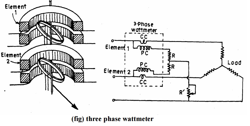
Three Phase Wattmeters
A dynamometer type three-phase wattmeter consists of two separate wattmeter movements mounted together in one case with the two moving coils mounted on the same spindle.
The arrangement is shown in Fig.
There are two current coils and two pressure coils.
A current coil together with its pressure coil is known as an element.
Therefore, a three phase wattmeter has two elements.
The connections of two elements of a 3 phase wattmeter are the same as that for two wattmeter method using two single phase wattmeter.
The torque on each element is proportional to the power being measured by it. The total torque deflecting the moving system is the sum of the deflecting torque of’ the two elements.
Hence the total deflecting torque on the moving system is proportional to the total Power.
In order that a 3 phase wattmeter read correctly, there should not be any mutual interference between the two elements.
A laminated iron shield may be placed between the two elements to eliminate the mutual effects.
Related Topics