Chapter: Distributed and Cloud Computing: From Parallel Processing to the Internet of Things : Computer Clusters for Scalable Parallel Computing
Single-System Image Features
Single-System Image Features
SSI does not mean a single copy of an operating system image residing in memory, as in an SMP or a workstation. Rather, it means the illusion of a single system, single control, symmetry, and transparency as characterized in the following list:
• Single system The entire cluster is viewed by users as one system that has multiple processors. The user could say, “Execute my application using five processors.” This is different from a distributed system.
• Single control Logically, an end user or system user utilizes services from one place with a single interface. For instance, a user submits batch jobs to one set of queues; a system administrator configures all the hardware and software components of the cluster from one control point.
• Symmetry A user can use a cluster service from any node. In other words, all cluster services and functionalities are symmetric to all nodes and all users, except those protected by access rights.
• Location-transparent The user is not aware of the where abouts of the physical device that eventually provides a service. For instance, the user can use a tape drive attached to any cluster node as though it were physically attached to the local node.
The main motivation to have SSI is that it allows a cluster to be used, controlled, and main-tained as a familiar workstation is. The word “single” in “single-system image” is sometimes synon-ymous with “global” or “central.” For instance, a global file system means a single file hierarchy, which a user can access from any node. A single point of control allows an operator to monitor and configure the cluster system. Although there is an illusion of a single system, a cluster service or functionality is often realized in a distributed manner through the cooperation of multiple compo-nents. A main requirement (and advantage) of SSI techniques is that they provide both the perfor-mance benefits of distributed implementation and the usability benefits of a single image.
From the viewpoint of a process P, cluster nodes can be classified into three types. The home node of a process P is the node where P resided when it was created. The local node of a process P is the node where P currently resides. All other nodes are remote nodes to P. Cluster nodes can be configured to suit different needs. A host node serves user logins through Telnet, rlogin, or even FTP and HTTP. A compute node is one that performs computational jobs. An I/O node is one that serves file I/O requests. If a cluster has large shared disks and tape units, they are normally physi-cally attached to I/O nodes.
There is one home node for each process, which is fixed throughout the life of the process. At any time, there is only one local node, which may or may not be the host node. The local node and remote nodes of a process may change when the process migrates. A node can be configured to provide multiple functionalities. For instance, a node can be designated as a host, an I/O node, and a compute node at the same time. The illusion of an SSI can be obtained at several layers, three of which are discussed in the following list. Note that these layers may overlap with one another.
• Application software layer Two examples are parallel web servers and various parallel databases. The user sees an SSI through the application and is not even aware that he is using a cluster. This approach demands the modification of workstation or SMP applications for clusters.
• Hardware or kernel layer Ideally, SSI should be provided by the operating system or by the hardware. Unfortunately, this is not a reality yet. Furthermore, it is extremely difficult to provide an SSI over heterogeneous clusters. With most hardware architectures and operating systems being proprietary, only the manufacturer can use this approach.
• Middleware layer The most viable approach is to construct an SSI layer just above the OS kernel. This approach is promising because it is platform-independent and does not require application modification. Many cluster job management systems have already adopted this approach.
Each computer in a cluster has its own operating system image. Thus, a cluster may display multiple system images due to the stand-alone operations of all participating node computers. Deter-mining how to merge the multiple system images in a cluster is as difficult as regulating many indi-vidual personalities in a community to a single personality. With different degrees of resource sharing, multiple systems could be integrated to achieve SSI at various operational levels.
1. Single Entry Point
Single-system image (SSI) is a very rich concept, consisting of single entry point, single file hierarchy, single I/O space, single networking scheme, single control point, single job manage-ment system, single memory space, and single process space. The single entry point enables users to log in (e.g., through Telnet, rlogin, or HTTP) to a cluster as one virtual host, although the clus-ter may have multiple physical host nodes to serve the login sessions. The system transparently distributes the user’s login and connection requests to different physical hosts to balance the load. Clusters could substitute for mainframes and supercomputers. Also, in an Internet cluster server, thousands of HTTP or FTP requests may come simultaneously. Establishing a single entry point with multiple hosts is not a trivial matter. Many issues must be resolved. The following is just a partial list:
• Home directory Where do you put the user’s home directory?
• Authentication How do you authenticate user logins?
• Multiple connections What if the same user opens several sessions to the same user account?
• Host failure How do you deal with the failure of one or more hosts?
Example 2.5 Realizing a Single Entry Point in a Cluster of Computers
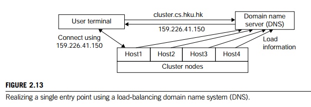
Figure 2.13 illustrates how to realize a single entry point. Four nodes of a cluster are used as host nodes to receive users’ login requests. Although only one user is shown, thousands of users can connect to the cluster in the same fashion. When a user logs into the cluster, he issues a standard UNIX command such as telnet cluster.cs.hku.hk, using the symbolic name of the cluster system.
The DNS translates the symbolic name and returns the IP address 159.226.41.150 of the least-loaded node, which happens to be node Host1. The user then logs in using this IP address. The DNS periodically receives load information from the host nodes to make load-balancing translation decisions. In the ideal case, if 200 users simultaneously log in, the login sessions are evenly distributed among our hosts with 50 users each. This allows a single host to be four times more powerful.
2. Single File Hierarchy
We use the term “single file hierarchy” in this book to mean the illusion of a single, huge file sys-tem image that transparently integrates local and global disks and other file devices (e.g., tapes). In other words, all files a user needs are stored in some subdirectories of the root directory /, and they can be accessed through ordinary UNIX calls such as open, read, and so on. This should not be confused with the fact that multiple file systems can exist in a workstation as subdirectories of the root directory.
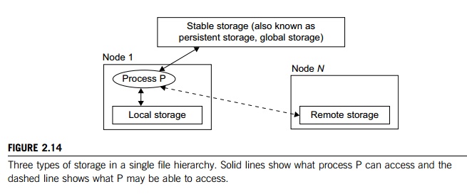
The functionalities of a single file hierarchy have already been partially provided by existing distrib-uted file systems such as Network File System (NFS) and Andrew File System (AFS). From the view-point of any process, files can reside on three types of locations in a cluster, as shown in Figure 2.14.
Local storage is the disk on the local node of a process. The disks on remote nodes are remote storage. A stable storage requires two aspects: It is persistent, which means data, once written to the stable storage, will stay there for a sufficiently long time (e.g., a week), even after the cluster shuts down; and it is fault-tolerant to some degree, by using redundancy and periodic backup to tapes.
Figure 2.14 uses stable storage. Files in stable storage are called global files, those in local sto-rage local files, and those in remote storage remote files. Stable storage could be implemented as one centralized, large RAID disk. But it could also be distributed using local disks of cluster nodes. The first approach uses a large disk, which is a single point of failure and a potential performance bottleneck. The latter approach is more difficult to implement, but it is potentially more economical, more efficient, and more available. On many cluster systems, it is customary for the system to make visible to the user processes the following directories in a single file hierarchy: the usual system directories as in a traditional UNIX workstation, such as /usr and /usr/local; and the user’s home directory ~/ that has a small disk quota (1–20 MB). The user stores his code files and other files here. But large data files must be stored elsewhere.
• A global directory is shared by all users and all processes. This directory has a large disk space of multiple gigabytes. Users can store their large data files here.
• On a cluster system, a process can access a special directory on the local disk. This directory has medium capacity and is faster to access than the global directory.
3. Visibility of Files
The term “visibility” here means a process can use traditional UNIX system or library calls such as fopen, fread, and fwrite to access files. Note that there are multiple local scratch directories in a cluster. The local scratch directories in remote nodes are not in the single file hierarchy, and are not directly visible to the process. A user process can still access them with commands such as rcp or some special library functions, by specifying both the node name and the filename.
The name “scratch” indicates that the storage is meant to act as a scratch pad for temporary information storage. Information in the local scratch space could be lost once the user logs out. Files in the global scratch space will normally persist even after the user logs out, but will be deleted by the system if not accessed in a predetermined time period. This is to free disk space for other users. The length of the period can be set by the system administrator, and usually ranges from one day to several weeks. Some systems back up the global scratch space to tapes periodically or before deleting any files.
4. Support of Single-File Hierarchy
It is desired that a single file hierarchy have the SSI properties discussed, which are reiterated for file systems as follows:
• Single system There is just one file hierarchy from the user’s viewpoint.
• Symmetry A user can access the global storage (e.g., /scratch) using a cluster service from any node. In other words, all file services and functionalities are symmetric to all nodes and all users, except those protected by access rights.
• Location-transparent The user is not aware of the whereabouts of the physical device that eventually provides a service. For instance, the user can use a RAID attached to any cluster node as though it were physically attached to the local node. There may be some performance differences, though.
A cluster file system should maintain UNIX semantics: Every file operation (fopen, fread, fwrite, fclose, etc.) is a transaction. When an fread accesses a file after an fwrite modifies the same file, the fread should get the updated value. However, existing distributed file systems do not completely follow UNIX semantics. Some of them update a file only at close or flush. A number of alternatives have been suggested to organize the global storage in a cluster. One extreme is to use a single file server that hosts a big RAID. This solution is simple and can be easily implemented with current software (e.g., NFS). But the file server becomes both a performance bottleneck and a single point of failure. Another extreme is to utilize the local disks in all nodes to form global storage. This could solve the performance and availability problems of a single file server.
5. Single I/O, Networking, and Memory Space
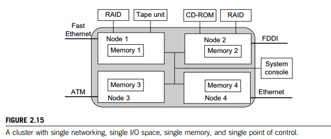
To achieve SSI, we desire a single control point, a single address space, a single job management system, a single user interface, and a single process control, as depicted in Figure 2.15. In this example, each node has exactly one network connection. Two of the four nodes each have two I/O devices attached.
Single Networking: A properly designed cluster should behave as one system (the shaded area). In other words, it is like a big workstation with four network connections and four I/O devices attached. Any process on any node can use any network and I/O device as though it were attached to the local node. Single networking means any node can access any network connection.
Single Point of Control: The system administrator should be able to configure, monitor, test, and control the entire cluster and each individual node from a single point. Many clusters help with this through a system console that is connected to all nodes of the cluster. The system console is normally connected to an external LAN (not shown in Figure 2.15) so that the administrator can log in remotely to the system console from anywhere in the LAN to perform administration work.
Note that single point of control does not mean all system administration work should be carried out solely by the system console. In reality, many administrative functions are distributed across the cluster. It means that controlling a cluster should be no more difficult than administering an SMP or a mainframe. It implies that administration-related system information (such as various configuration files) should be kept in one logical place. The administrator monitors the cluster with one graphics tool, which shows the entire picture of the cluster, and the administrator can zoom in and out at will.
Single point of control (or single point of management) is one of the most challenging issues in constructing a cluster system. Techniques from distributed and networked system management can be transferred to clusters. Several de facto standards have already been developed for network management. An example is Simple Network Management Protocol (SNMP). It demands an efficient cluster management package that integrates with the availability support system, the file system, and the job management system.
Single Memory Space: Single memory space gives users the illusion of a big, centralized main memory, which in reality may be a set of distributed local memory spaces. PVPs, SMPs, and DSMs have an edge over MPPs and clusters in this respect, because they allow a program to utilize all global or local memory space. A good way to test if a cluster has a single memory space is to run a sequential program that needs a memory space larger than any single node can provide.
Suppose each node in Figure 2.15 has 2 GB of memory available to users. An ideal single memory image would allow the cluster to execute a sequential program that needs 8 GB of memory. This would enable a cluster to operate like an SMP system. Several approaches have
been attempted to achieve a single memory space on clusters. Another approach is to let the compiler distribute the data structures of an application across multiple nodes. It is still a challenging task to develop a single memory scheme that is efficient, platform-independent, and able to support sequential binary codes.
Single I/O Address Space: Assume the cluster is used as a web server. The web information database is distributed between the two RAIDs. An HTTP daemon is started on each node to handle web requests, which come from all four network connections. A single I/O space implies that any node can access the two RAIDs. Suppose most requests come from the ATM network. It would be beneficial if the functions of the HTTP on node 3 could be distributed to all four nodes. The following example shows a distributed RAID-x architecture for I/O-centric cluster computing.
Example 2.6 Single I/O Space over Distributed RAID for I/O-Centric Clusters
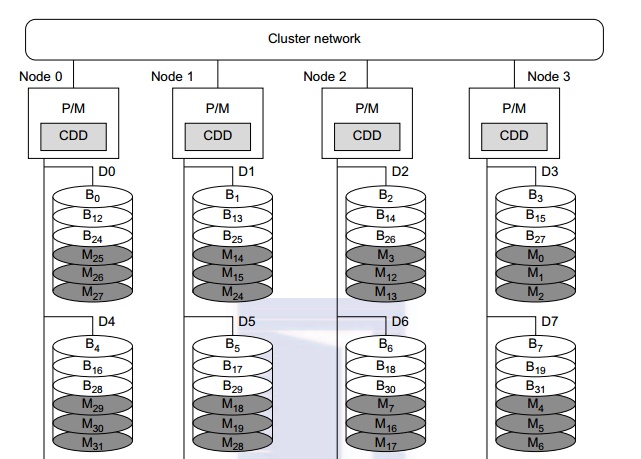
A distributed disk array architecture was proposed by Hwang, et al. [9] for establishing a single I/O space in I/O-centric cluster applications. Figure 2.16 shows the architecture for a four-node Linux PC cluster, in which three disks are attached to the SCSI bus of each host node. All 12 disks form an integrated RAID-x with a single address space. In other words, all PCs can access both local and remote disks. The addres-sing scheme for all disk blocks is interleaved horizontally. Orthogonal stripping and mirroring make it possi-ble to have a RAID-1 equivalent capability in the system.
The shaded blocks are images of the blank blocks. A disk block and its image will be mapped on dif-ferent physical disks in an orthogonal manner. For example, the block B0 is located on disk D0. The image block Mo of block B0 is located on disk D3. The four disks D0, D1, D2, and D3 are attached to four servers, and thus can be accessed in parallel. Any single disk failure will not lose the data block, because its image is available in recovery. All disk blocks are labeled to show image mapping. Benchmark experi-ments show that this RAID-x is scalable and can restore data after any single disk failure. The distributed RAID-x has improved aggregate I/O bandwidth in both parallel read and write operations over all physical disks in the cluster.
6. Other Desired SSI Features
The ultimate goal of SSI is for a cluster to be as easy to use as a desktop computer. Here are addi-tional types of SSI, which are present in SMP servers:
• Single job management system All cluster jobs can be submitted from any node to a single job management system.
• Single user interface The users use the cluster through a single graphical interface. Such an interface is available for workstations and PCs. A good direction to take in developing a cluster GUI is to utilize web technology.
• Single process space All user processes created on various nodes form a single process space and share a uniform process identification scheme. A process on any node can create (e.g., through a UNIX fork) or communicate with (e.g., through signals, pipes, etc.) processes on remote nodes.

• Middleware support for SSI clustering As shown in Figure 2.17, various SSI features are supported by middleware developed at three cluster application levels:
• Management level This level handles user applications and provides a job management system such as GLUnix, MOSIX, Load Sharing Facility (LSF), or Codine.
• Programming level This level provides single file hierarchy (NFS, xFS, AFS, Proxy) and distributed shared memory (TreadMark, Wind Tunnel).
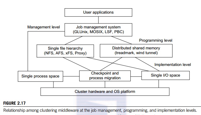
• Implementation level This level supports a single process space, checkpointing, process migration, and a single I/O space. These features must interface with the cluster hardware and OS platform. The distributed disk array, RAID-x, in Example 2.6 implements a single I/O space.
Related Topics