Chapter: Electrical Drives & Control : Drive Motor Characteristics
Single Phase Induction Motors: Construction, Working Principle, Electric Braking, Torque Slip Curve
SINGLE PHASE INDUCTION MOTORS
Why a single phase induction motor does not self start?
· When a single phase supply is fed to the single phase induction motor.
· Its stator winding produces a flux which only alternates along one space axis.
· It is not a synchronously revolving field, as in the case of a 2 or 3phase stator winding, fed from 2 or 3 phase supply.
Types :
The types of single phase induction motors are:
i. Split phase induction motor.
ii. Capacitor start induction motor.
iii. Capacitor start and capacitor run motor.
iv. Shaded pole induction motor.
1. CONSTRUCTION AND WORKING PRINCIPLE
CONSTRUCTION:
· Similar to a D.C. motor single phase induction motor has basically two main parts one rotating and other stationary.
The stationary part in single phase induction motors is called stator while the rotating part is called rotor.
The Stator has laminated construction made up of stampings.
The stampings are slotted on its periphery to carry the winding called stator winding or main winding. This is excited by a single phase a.c, supply.
The laminated construction keeps iron losses to minimum.
The stampings are made up of material like silicon steel which minimizes the hysteresis loss.
The stator winding is wound for certain definite number of poles means when excited by single phase a.c. supply stator produces the magnetic field which creates the effect of certain definite number of poles.
The number of poles for which stator winding is wound decides the synchronous speed of the motor.
The synchronous speed is denoted as N, and it has a fixed relation with supply frequency f and number of poles P. The relation is given by,

The induction motor never rotates with the synchronous speed but rotates at a speed which is slightly less than synchronous speed.
The rotor construction is of squirrel cage type.
In this type rotor consists of un insulated copper or aluminium bars placed in the slots.
The bars are permanently shorted at both ends with the help of conducting rings called end rings. The entire structure looks like cage hence called squirrel cage rotor.
The construction and symbol is shown in the Fig. 1
As the bars are permanently shorted to each other the resistance of the entire rotor is very small.
The air gap between stator and rotor is kept uniform and as small as possible.
The main feature of this rotor is that of the stator winding.
The schematic representation of two pole single phase induction motor is shown in the Fig. 2.
Working Principle:
· For the motoring action there must exists two fluxes which interact with each other to produce the torque.
· In D.C. motors field winding produces the main flux while d.c. supply given to armature is responsible to produce armature flux.
· The main flux and armature flux interact to produce torque.
· In the single phase induction motor single phase a.c. supply is given to the stator winding.
· The stator winding carries an alternating current which produces the flux which is also alternating in nature.
· This flux is called main flux.
· This flux links with the rotor conductors and due to transformer action emf. gets induced in the rotor.
· The induced emf. drives current through the rotor as rotor circuit is closed circuit.
· This rotor current produces another flux called rotor flux required for the motoring action.
· Thus second flux is produced according to induction principle due to induced emf. hence the motor is called induction motor.
· As against this in D.C. motor a separate supply is required to produce armature to flux.
· This is an important difference between d.c motor and an induction motor.
Key Point: Another important difference between the two is that the D.C. motors are self starting while single phase induction motors are not self starting.
2. TORQUE-SLIP CURVE FOR INDUCTION MOTOR
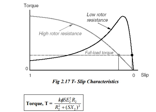
When S = 0, T =0. Hence curve starts from point 0.
At normal speeds, close to synchronism the terms (SX2) is small an hence negligible with respect to R2.
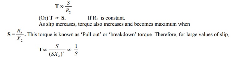
Hence, torque/slip curve is a rectangular hyperbola.
3. ELECTRIC BRAKING IN AC INDUCTION MOTOR
Braking on AC induction motors
· Regenerative braking
· Dynamic braking
· Plugging(op)counter current braking
Regerative braking
In the regerative braking the energy is returned to the supply, is possible if the motor runs faster that its synchronous speed.
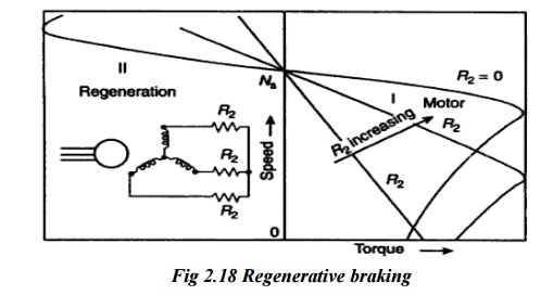
The motor torque approach to zero as the motor begins to approach the no load speed i.e the synchronous speed
The further increase in the motor speed, the motor will acts as a generator ,connected in parallel to the supply and ill return electric energy.
The regenerative braking operation is represented by the portions of the speed torque characteristics extended into the second quadrant.
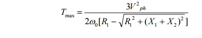
The maximum torque developed on regenerative braking operation will react a higher value than on motoring operation .This can be calculated as below,
The application of this braking are in crane hoists, excavators etc.
Dynamic braking
Dynamic braking of an induction motor is used achieved by switching over its starter to a DC supply and shunting the rotor external resistance.
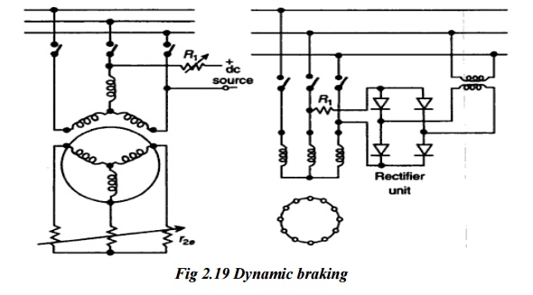
To perform dynamic braking the switch Sw1 is opened and cut off a.c apply the DC power. for limiting the current the rotor is connected to a suitable resistor Rb .
The flow of direct current sent through the starter winding sets up a stationary magnetic flux.
Rotation of the rotor in this field will produces a flow of induced alternating current in the rotor which also sets up a magnetic field, stationary with respect to the stater.
Due to the interaction of the resultant magnetic field set up by the stator winding ,the rotor circuit resistance and the speed of the rotor.
Speed torque characteristics of the induction motor under dynamic braking
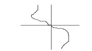
The speed torque characteristics of the induction motor under this braking conditions lies in the second quadrant of the speed torque phase.
If the effect of saturation is neglected, the magnitude of the maximum torque developed will be directly proportional to the square of the voltage applied to the starter.
G. Plugging
The counter braking is widely used in drives .the counter current braking condition can be setup when the torque TL is greater than Tst‟
i.e TL>Tst
where,
TL=load torque
Tst=starting torque
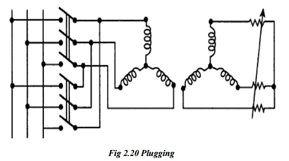
To limit the current and develop the braking torque a resistance is introduced in to the rotor circuit.
Under this counter-current braking the steady-state operation will correspond to the point ()on the characteristics.
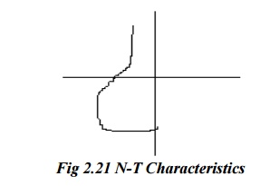
Speed torque characteristics of induction motor under counter current braking
A counter –current braking condition can also be set up by interchanging the supply leads of any two phases of the starter winding to reverse the direction of rotation of the motor field with the rotor still rotation in the initial direction.
since the rotor rotation is now opposed by a torque acting in the opposite direction, the rotor begins to slow down. when the speed drops to zero, the motor should be de-energized, otherwise, it will again begin motoring and cause the rotor to run in the opposite direction.
Related Topics